The Return Path on a Transmission Line
To understand the return path of a transmission line let us understand the mechanism of the flow if current and voltage across a capacitor. The figure below shows a capacitor with a voltage source. If the voltage source is a DC source there is no flow of current in the. If the DC voltage is V volts, then there will be voltage V across the capacitor. But there is no flow current in the circuit, if we think of the steady state.
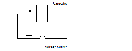
Figure - Flow of current in a Capacitor
Now think of supplying a ramp voltage wave to this circuit. The ramp wave is such that at t = 0, the voltage v = 0, and at t = T, the voltage v = V.
Assume that the left hand side of the voltage source is positive. When the voltage at terminal at the left hand side starts rising, there is a flow of current from the left side of the voltage source to the left hand side of the capacitor as shown by arrow in the figure above. Thinking in terms of electrons, the electrons start to flow from the left edge of the capacitor to the left side (+ve) of the voltage source. As the electrons depart from the left side (left plate) of the capacitor, it becomes positively charged. It now attract the electrons from the right hand plate of the capacitor. As the electrons on the right plate of the capacitor are attracted by the left plate, there is a flow of electron from the right side of the voltage source ( negative plate) to the right plate of the capacitor. In other words, there is a flow of electrons from the right side of the voltage source ( -ve end) to the right plate of capacitor. In terms of the direction of current there is a flow from the right side of the capacitor to the right side of the voltage source.
This happens only during the ramp of the voltage. Once the voltage change stops, the current flow stops. We will apply this understanding to know how the current flows in a microstrip.
Assume a microstrip just over a ground power plane. It is immaterial for immediate discussion whether the other end of the microstrip is open or short. We make this microstrip arbitrarily long. Long enough so that it will take five minutes to travel from one end to other. If it has to be from Sun to Mars, let it be. While the signal takes 5 minutes to travel from one end to under, let us take our time to understand the mechanism.
Consider the a signal of 100 ps rise time launched into the left side of the microstrip. We can think of a number capacitors placed between the microstrip trace and the return ground plane. Consider, first tiny capacitor. As the rising edge signal is at the top edge of the first capacitor, there is a flow of current from the edge of the microstrip to the top edge of the capacitor. In terms of the electron flow, it means that there is a flow of electron from the top edge of the capacitor to the left hand side towards the voltage sources.
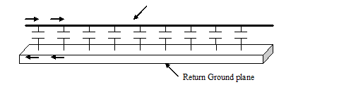
Figure - Propagation of Signal through a Microstrip.
As the electrons depart from the top edge of the first capacitor, the top edge pulls the electrons of the bottom edge of the capacitor. This makes the electrons flow from the left edge of the ground plane to bottom plate of the capacitor. In terms of the current, it means that there is a flow of current from the bottom edge of the capacitor to the left edge of the ground plane.
This keeps happening to the next capacitor as the signal propagates. Notice that there is a voltage propagation as well as a current propagation.
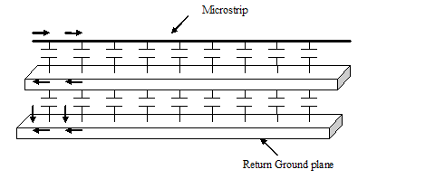
Figure Return Current with a metal plane in between
We will now consider the case when the plane beneath the signal trace is not a ground plane, but just a metallic plane. The ground plane lies under the metallic plane say, 5 mils below it. The area between the metallic plane and the ground plane is filled with some thin dielectric material. We will now see how the current returns in this scenario. As usual, we will launch the 100 ps rise time signal at the left end of the microstrip.
As earlier, assume that the space between the microstrip and the metal plate has a number of small capacitors. Similarly, the space between the metal plate and the return ground plate can be assumed to have a number of tiny capacitor spaced a at slight distance.
When the rising edge of the signal starts propagating the microstrip, there is a accumulation of positive charge on first capacitor between the microstrip and the metal plate. As a result of this, the end of the capacitor connected to the metal layer gets negatively charged. As a result of this the other end of the metal plate becomes positively charged. We can therefore think of the first capacitor between the metal layer and the ground layer to be positively charged at the metal layer end and negatively charged at the return ground plane layer end (facing the return ground plane). We finally see that this structure results in the current flow similar to the case when there is a flow of the signal between the top layer and the ground layer. The metal layer just couples the signal from the top layer to the bottom return layer. There is an ac short between the metal layer and the bottom ground layer.
Previous - Impedance Calculator in Allegro Impedance Between Power Planes