Chpater 13- Designing for EMI Complicance
Once the product is tested at the lab and its functionality is as expected, it is time to take the product for the EMI/EMC compliance test. If you want to sell your product, it must obey some legal obligations. In United States of America FCC ( Federal Communications Commission) specifies the limits of maximum amount of radiation a product can generate. Canada has DOC, and Europe has EMC-Regulation, which must be met. Other countries have similar regulations.FCC has two classes of products based upon the amount of radiation they are allowed. The radiation limit for Class A products are less stringent. Class A products are those that are meant to be used only in industrial and manufacturing environment. A product designated as Class A is not intended to be sold in home or residential areas. They are allowed to radiate more. The radiation limits for Class B products are more stringent. Class B products are those that are meant to be used in home and office environment.
For Class A products, the radiated electric fields are measured at a distance of 10 meters from the product. The Table below gives the maximum radiated field strength for class A products.
Table : FCC Class A Emission Limits
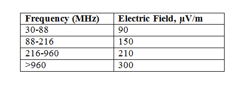
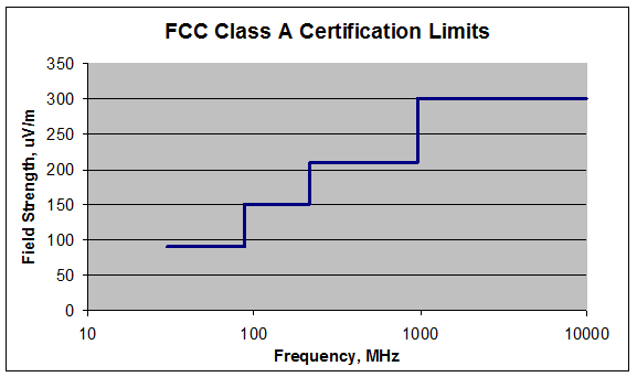
Figure - FCC Class A Certification Limits Field Strength at a distance of 10 meters
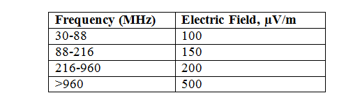
For Class B, the radiated electric fields are measured at a distance of 3 meters from the object.
Table - FCC Class B Emission Limits
Sometimes the Emission levels are mentioned in dBµV/m. The chart below gives the emission limits in dBµV/m.
Table Class B Emission Limits in dBµV/m
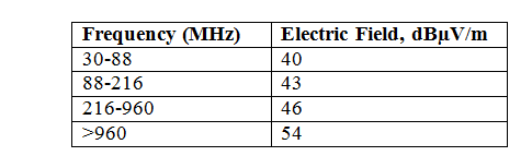
Following formula can be used for conversion from µV to dBµV
Value in dBµV = 20 log10(Value in µV/1µV)
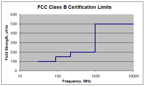
Figure FCC Class B Certification Limits Field Strength at a distance of 3 meters.
On the first day you take your equipment to the EMI laboratory, the lab personal will run a quick radiation test. It will test for any unintentional radiation from your equipment. If your equipment has been designed well it should be within the specified limits. Here is how a typical curve may look like.

Figure A Typical EMI Curve for an equipment passing EMI Class B Limits.
An Approximation of Electric Field from A Current Loop Antenna
We can estimate the electric field strength from a signal trace by approximating the trace carrying current as a monopole antenna.
The maximum electric filed strength from an antenna formed by a current loop source is given by [ Introduction to Electromagnetic Compatibility, Clayton R. Paul]
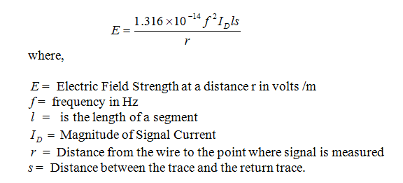
For FCC Class B, the distance r is fixed as 3 meter. Here are some important conclusions that we can draw.
1. The Longer is the length of the trace the larger is the emission level. Doubling the trace length doubles the amount of the radiation.
2. The Larger is the separation of between the trace and the return current the more is the amount of the radiation.
3. Higher current in the trace segment generates more radiation.
Example Consider a ribbon cable of length 50 cm carrying a current of 5 mA. The separation between the adjacent wires of the ribbon cable is 0.1. Assuming the return current in the adjacent conductor, estimate the maximum electric field strength at a distance of 3 meter from the Ribbon Cable for a frequency of 200 MHz
Solution - The Electric field is given by,
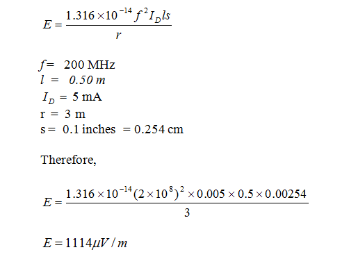
FCC Class B has a limit of 150 µV/m at a frequency of 200 MHz. This cable carrying 200 MHz frequency is therefore unsuitable and is likely to fail EMI test. Some options to consider will be to use smaller length, reduce the maximum allowed frequency in this cable. A different cable design that reduces the separation between the adjacent wires will also reduce the radiated field.
Previous Next