Verilog Full Adder Example
| Full Adder |
We will continue to learn more examples with Combinational Circuit - this time a full adder. A combinational circuit is one in which the present output is a function of only the present inputs - there is no memory. This is different from the sequential circuits that we will learn later where the present output is a function of not only the present input but also of past inputs/outputs as well.
Table: A one bit comparator
| Carry in | Input y | Input x | Carry out | Output A |
| 0 | 0 | 0 | 0 | 0 |
| 0 | 0 | 1 | 0 | 1 |
| 0 | 1 | 0 | 0 | 1 |
| 0 | 1 | 1 | 1 | 0 |
| 1 | 0 | 0 | 0 | 1 |
| 1 | 0 | 1 | 1 | 0 |
| 1 | 1 | 0 | 1 | 0 |
| 1 | 1 | 1 | 1 | 1 |
Let us look at the source code for the implemmentation of a full adder
fulladder.v
|
The important statement to note is the assignment statement
assign {cout,A} = cin + y + x;
An left side of the assignemnt statement can contain a concatenation of scalar or vector. In this way it is possible in this case to assign the result of the adder to two bit vector. Notice how the vector array is formed using the curly bracket {cout,A}. The rightmost part of the vector {cout,A} , which is A in this case forms the LSB.
We will now add a test bench to confirm that the result is as expected. So here goes the test bench.
fulladdertb.v
|
As usual we will compile the program with following commands
C:\iverilog -o output fulladder.v fulladdertb.v
C:\vvp output
time =  0, CIN =0, IN1=0, IN2=0, COUT=0, OUT=0
time = 20, CIN =0, IN1=0, IN2=1, COUT=0, OUT=1
time = 40, CIN =0, IN1=1, IN2=1, COUT=1, OUT=0
time = 60, CIN =0, IN1=1, IN2=0, COUT=0, OUT=1
time = 80, CIN =1, IN1=1, IN2=0, COUT=1, OUT=0
time = 100, CIN =1, IN1=0, IN2=0, COUT=0, OUT=1
time = 120, CIN =1, IN1=0, IN2=1, COUT=1, OUT=0
tme = 140, CIN =1, IN1=1, IN2=1, COUT=1, OUT=1
Notice that we have introduced a system variable $time as one of the parameters in the $monitor statement. This comes handy when looking at the data ( if that is not in graph).
The system variable $time returns the current simulation time as a 64-bit integer.
Looking back at the code - the vector concatenation thing on the left hand side in the assignment statement
assign {cout,A} = cin + y + x;
Could be replaced by two assignment statements ( looking at the table in the top of the page and writing sum of products.
assign A =  ((~cin) & x &(~y)) | ((~cin) &(~x)&y ) | (cin &(~x) &(~y)) | (cin & x & y)     ;
assign cout = ((~cin) & x &y) | ((cin) &(~x)&y ) | (cin &(x) &(~y)) | (cin & x & y)  ;
If you look more closely, the full adder circuit can be simplified quite a bit, but will require intelligent mix of
Exclusive OR gates when writing term for sum.
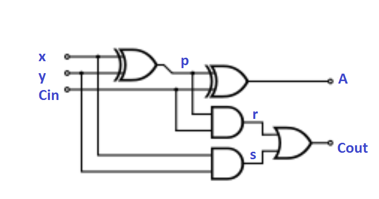
This will form the basis of one of the exercises below.
| Exercise |
1. Redo the full adder with Gate Level modeling. Run the test bench to make sure that you get the correct result.
2. Draw a truth table for full adder and implement the full adder using UDP.
3. Use the waveform viewer so see the result graphically.
| Solution |
Before looking at the solution, make sure you have given your efforts to solve it. Here are the solution codes.
|
|
Exercise
1. Extend the full bit adder so that it can add two 2 bit inputs in place of two 1 bit inputs. It will also have a carry in and a carry out.