Verilog case statement in Combinatorial circuit
| case statement |
When the number of the nesting grows, it becomes difficult to understand the if else statement. The verilog case statement, comes handy in such cases. We will first look at the usage of the case statement and then learn about its syntax and variations.
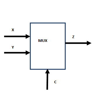
We had earlier written a simple multiplexer. A multiplexer selects one of several input signals and forwards the selected input to a single output line.
A single bit multiplexer will have one control line two inputs ( say X and Y) and one output ( say Z). When the control is 0, X is connected to Z. When the Control is 1, Y is connected to Z.
The figure below explains this
Let write this example using verilog case statement
|
Note that we had to assign out as a register in
reg out;
This is because we need to assign values to it explicitly and not drive them. This is called procedural assignment. We can not assign a wire data type explicitly. The previous example we had done using a continuous assignment statement. The case statement
out = in1;
Could have a begin and end as in
begin
out = in1;
end
In our case, it was not required because we had only one statement. We now suggest that you write a test bench for this code and verify that it works. If you have difficulty, you can check it with following test bench
|
case  [case-expr}
[item]  :
begin
[procedural statementl  ;
[procedural statementl  ;
. .  .
end
[item]  :
begin
[procedural statement  1  ;
[procedural statement  1  ;
.  . .
end
[iteml  :
begin
[procedural statement  1  ;
[procedural statementl;
end
. . .
default:
begin
[procedural statement  1  ;
[procedural statementl;
end
endcase
Let us now take a look at another example. This time we will rewrite the priority encoder example we presented in the previous section using the case statement. Recall the table for a 4 input priority encoder
Table: A priority encoder with 4 Inputs
| x[4] | x[3] | x[2] | x[1] | Output z |
| 1 | - | - | - | 100 |
| 0 | 1 | - | - | 011 |
| 0 | 0 | 1 | - | 010 |
| 0 | 0 | 0 | 1 | 001 |
| 0 | 0 | 0 | 0 | 1 |
When the x[4] input is 1, it has highest priority and irrespective of the values of other bits, we will give the output that corresponds to the binary digit corresponding to 4 in x[4] or 100. Similarly, if the x[4] is zero and the priority of the next bit x[3] is high, then irrespective of the values of x[2] and x[1], we give output corresponding to 3 of x[3] - or 011. We follow the same logic as per the table above.
Let us now write the actual verilog code that implement the priority encoder using case statements
|
Note that the always statement
always @(x[4], x[3],x[2], x[1])
Could be written as
always @ *
We now suggest that you write a test bench for this code and verify that it works. If you have sifficulty, you can check it with following test bench
|
Notice the use of the case statement
4'b1000, 4'b1001 , 4'b1010, 4'b1011 , 4'b1100 , 4'b1101, 4'b1110 , 4'b1111 :
pcode  = 3'b100;
When the vale of x matches any of the following values
4'b1000, 4'b1001 , 4'b1010, 4'b1011 , 4'b1100 , 4'b1101, 4'b1110 , 4'b1111 :
The statement next to it
pcode = 3'b100;
is executed. Notice that this could also be have been written as
4'b1000, 4'b1001 , 4'b1010, 4'b1011 , 4'b1100 , 4'b1101, 4'b1110 , 4'b1111 :
begin
pcode  = 3'b100;
end
The
boolean-expr is evaluated and if it is true, the list of the procedural statements between begin and end
is executed. If the boolean-expr
is false the procedural statements in the else block is executed. The begin and end can be omitted if there is only one procedural statement as
in the case of our example. The else statement can become else statement if we wish to check second condition.
A Binary Decoder Example |
We will now present another example that will make use of
if statement. A Binary decoder is a circuit that has n inputs and 2n outputs.
It asserts one and only one 2n outputs depending upon the input.
Let us say our binary decoder has 2 inputs x[1] and x[0] and 4 outputs y[3], y[2], y[1], y[0].
We are also making the decoder circuit a bit more complicated by requiring an enable signal. If the enable is 0 ( means it is disabled), the output will be 4'b0000.
The table below shows the function of the Binary decoder.
Table: A 2 to 4 binary Decoder with Enable Signal
| Enable | x[1] | x[0] | Output y[3:0] |
| 0 | - | - | 0000 |
| 1 | 0 | 0 | 0001 |
| 1 | 0 | 1 | 0010 |
| 1 | 1 | 0 | 0100 |
| 1 | 1 | 1 | 1000 |
Can you now try to implement the above on your own without looking at the code presented below.
|
Note that the if statement
if (enable == 1'b0)
Could also be written as
if (~enable)
We now suggest that you write a test bench for this code and verify that it works. If you have sifficulty, you can check it with following test bench
|
| Exercise |
1. Run the Multiplexer example, but at this time we should have 2 control bits, 4 input pins and 1 output pin. One of the 4 inputs will be connected to the output depending upon the control bit. Check the solution here