Verilog Comparator example
In our first verilog code, we will start with the design of a simple comparator to start understanding the Verilog language. This will extend our "Hello World" example to create something useful. Let us take a look at the following table which describes the behaviour of a comparator circuit.
Table: A one bit comparator
| Input x | Input y | Output z |
| 0 | 0 | 1 |
| 0 | 1 | 0 |
| 1 | 0 | 0 |
| 1 | 1 | 1 |
Basically when both the inputs x and y are same, the output z is 1. When the inputs are unequal, the output is 0.
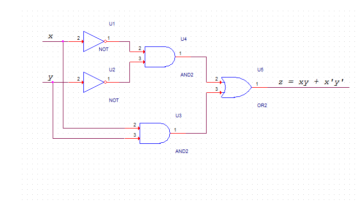
We can describe the circuit using AND, NOT and OR gates using the following equation.
assign z = (~x & ~y) |(x & y);
where ~x and ~y represent the complements of x and y respectively.
The following shows a circuit that implements this logic.
And here is the verilog code that implements this logic
|
We will try to make you understand what Verilog is - in a matter of one day. At least you should be able to compile and run verilog code. We hope that this is something you will be able to achieve within next few pages. Throughout this tutorial we will present you enough examples and exercises so that you have a good grip over the language as well as the verilog concepts.
While Verilog has concurrent blocks executing in parallel, it is still similar to software programming language like C.
If you have closely watched the schematics above and the verilog code below it, you must have appreciated how verilog simplifies the process of hardware design. Before the advent of Verilog, everything was done using schematics. The Schematics were error-prone, difficult to verify and had long process of design, verification, fix, redesign and re verify.
With Verilog the whole dimension and process of hardware circuit design changed. This provided a new kind of abstraction where the details of implemmentation are separated. Verilog design is more like a software programming, but, you must also have a strong understanding of the circuit that works behind the code.
Let us now understand the code. Take a look at
module comparator( input x, input y, output z ); |
Verilog consists of modules. Inside the modules we have a list of ports ( or pins). A port can be an input or an output depending upon its direction. A pin can also be defined as bidirectional using inout.
The direction can also be specified out of the module. This code is equivalent to the previous code.
module comparator( x, y, z ); input x; input y; output z; |
Let us now take a look at the assign statement
assign z = (~x & ~y) |(x & y); |
This implements a combinational logic. An assign statement is used for modeling only combinational logic. The statement in the assign statement is executed continuously ( as against those that trigger on a clock). An assign statement is also called 'continuous assignment statement'.
This statement implements the comparator logic that we had shown earlier in example.
In the next page we will see how to test this code using the simulation.