Tom - Bob - Chapter 7
7.9 Tom and BobTom Hey Bob, my circuit has lot of noise in power supply. I can feel it. When I put my oscilloscope probe, I can see a lot of power supply noise the power and the ground planes even when I placed the active pin of the probe very close to the ground wire of the probe. How can I design such that there is no noise between the power and ground rails.
Bob You have taken one good step. You have put up a scope and observed the noise. This is the beginning. You have an analytical and sensitive mind. If there is a noise it can be suppressed by the use of capacitors. A capacitor provides a low impedance path between the power and ground rail. Because of the low impedance path, the ac noise on the power rail gets shorted with the ground.
Tom I see. I do understand that a capacitor is helpful in ensuring a smooth power supply. But what is this low impedance path? How does a capacitor provide a low impedance path?
Bob - I am glad to know you understand the importance of capacitor in suppressing the noise. You understand its need. The only other thing you need is the ability to quantitatively specify the value and number of the capacitors required. As far as the low impedance path provided by a capacitor is concerned, consider the circuit below.

The impedance of a capacitor is given by
Xc= 1/ 2*pi*fc Where,
XC = Impedance in Ohms,
f = frequency,
C = Capacitance in Farad
Now XC is very low if the frequency f is high and/or C is high. As an example, if C = 0.1µF and f = 100 MHz, then
Xc= 1/(2*pi*100*10e6*0.1*10e-6) XC = 0.016 Ohms
This is indeed very low impedance. It will essentially mean that if 100 MHz noise is present at power rail it should get shorted to ground by the low impedance path.
Tom OK. OK. So you said that you can provide a low impedance path by using a capacitor. I use a big capacitor, say 1000 µF. My uncle has a factory that makes 1000 µF capacitors. I will use one of those in my design. With this capacitor I have
Xc= 1/ 2*pi*fc
Now at f = 10 KHz
or,
XC = 0.016 Ohms
Also at f = 100 GHz Xc= 1/(2*pi*100*10e9*1000*10e-6)
or,
XC = 0.0016 micro Ohms
So I keep improving my performance at higher frequencies. I have very low impedance at all frequencies from 10 KHz to 100 GHz. If frequency is higher than 100 GHz, its performance will be even better at it will have even lower impedance.
Bob Oh Tom, you are an excellent observer. Your going to extremes to ask questions make me happy. That is the way to learn. You can not learn by just monotonically reading. You have to take the assumptions to extremes to understand.
Now, you have designed a power supply decoupling system that works till 100 GHz. Let me congratulate you on your observation that the impedance decreases with the increase in frequency. At 100 GHz it is even better. In fact, with your observation, your power supply decoupling system gets better at higher frequency. As per your observation we should not worry about higher frequency noise at all. XC gets lower and lower at higher and higher frequency. All we need to worry about is the lower frequency where XC will be somewhat higher as frequency f will be lower.
The reasoning is totally justified, but O Tom, there are evil things in the world and we need to fight them out. This time the enemy is parasitic inductance of the capacitor. A 1000 µF capacitor that your uncle makes has a parasitic inductance close to 10 nH. This inductance becomes our enemy at higher frequencies. A 1000 µF capacitor, such as the one that your uncle makes can be modeled as an inductor in series with a Capacitor.
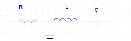 Figure 7 6 A real capacitor with parasitic inductance L and series resistance R
Now, the impedance of this structure is given by
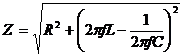
Where,
Z = Impedance in Ohms,
f = frequency in Hz,
C = Capacitance in Farad
L = Parasitic inductance of the Capacitance in Henry, also called ESL
R= Effective Series Resistance (ESR) of the capacitor
Now calculate your impedance again at 100 GHz. At 100 GHz, the impedance term due to the capacitance is simply dwarfed. Let us calculate the impedance at 100 GHz. Let us ignore the ESR for now.
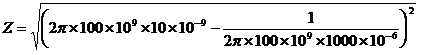 or,
or,Z= 6.28 Kilo Ohms
At 100 GHz, you capacitor has an impedance of 6.28 Kilo Ohms. This is as good as open for the purpose of power supply decoupling. All noise coming into the power supply rail will not be shorted to ground it will go directly to IC.
Forget 100 GHz, even at 100 M Hz, there will be 6.28 Ohm impedance. Many microprocessor supplies can not tolerate that much of impedance. You need much lower impedance.
Tom Bob that was helpful. I can now see my enemy the inductance. If I ask my uncle to make a 1000 µF capacitor with zero inductance, it will solve my problem. Correct ?
Bob Yes it will, if your uncle could design a capacitor with 1000 µF capacity and no parasitic inductance. However, as the capacitor start growing in size, its leads and mechanical structure gets bigger and bigger. And therefore, you will usually see larger parasitic inductance rather than lower parasitic inductance at higher capacitor value. But I admire your vision of 1000 µF capacity and no parasitic inductance.
Many companies are trying to research to make capacitors with as low parasitic inductance as possible. Even if it is possible to get capacitances with zero inductance, there will be trace inductance connecting the capacitor to the power and ground rails. These trace inductance prevent low impedance at higher frequency.
Tom - Bob, pardon me for my excesses on 1000 µF capacity and 100 GHz frequency extremes. And thanks for pointing out un practicality of producing an inductor less 1000 µF capacitor. Now tell me
- If 100 GHz is an extreme, what is the reasonable frequency range for which, I should target to achieve low impedance.
- What is a reasonable low impedance value.
Bob Tom, now we are in a real and practical discussion. Most of the modern processor based systems need clean supply free from noise till 1 GHz. For many of them adequate low impedance till 300 MHz will work.
As for the low impedance value is concerned, I will say the lower the better. A value of 0.005 Ohm is a reasonably good number. The requirements of processors are becoming more and more demanding and some of them need as low as 0.001 Ohm impedance between power and ground rails. Now you know the ball park number. It is between 0.01 to 0.001, the lower, the better.
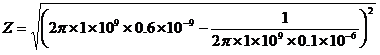
Tom Bob, that seems easy. I see the problem with high value capacitor. They have high inductance. So now I am choosing 0.1 µF capacitors. I checked that their parasitic inductance is 0.6 nH.
Now I am calculating their impedance at 1 KHz.
Now neglecting the ESR,
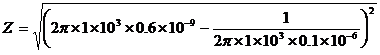
Z = 1592 Ohms
Such a capacitor is useless Bob if we have a noise at 1 KHz at power supply rail. Isnt it Bob.
Bob - Your observation is exactly correct. The 0.1 µF capacitor is useless to filter 1 KHz noise on the power rail. That is why you need a high 1000 µF capacitor. It has low impedance at 1 KHz. This way your uncle will not get out of business. The 0.1 µF capacitor will have its use at higher frequency.
Tom Oh, I am very happy to know my Uncle will not get out of business with his capacitor factory. He has promised me a job after I complete my understanding of this high speed design stuff.
Now that this 0.1 µF capacitor is useless for filtering low frequency noise of at 1 KHz, I am going to use it for high frequency filtering. Let me see how it performs at 1 GHz.
Neglecting the ESR,
Z = 3.77 Ohms
You had said that we need 0.001 Ohms for most of todays system designs. This 3.77 Ohms at 1 GHz means this capacitor is useless at high frequency.
You had earlier said that this capacitor is useless at lower frequency and I have to use my uncles 1000 µF capacitor at lower frequency. Now I see that it is useless at higher frequency of 1 GHz too. If this capacitor is not useful at low frequency, if this capacitor is not useful at high frequency, then O Bob, what the heck this whole world keeps using this 0.1 µF capacitor in hundreds of numbers in each of their designs.
Bob O Tom, going to extremes is good for beginners. It is good to start, but as you become more and more accomplished, you have to see in between.
Look at the impedance of capacitor
For this case of the 0.1 µF Capacitor, we have
L = 0.1 nH
C = 0.1 µF
Let us also assume some realistic value of the ESR for this capacitor. A 0.1 µF capacitor has a typical ESR value of 0.05 Ohms.
Now impedance Z is a function of frequency f . So what we need to do is to plot a curve which shows variation of Z with respect to the frequency f. Here is the curve. I have generated this curve using Microsoft XL sheet. First I created a column which had frequency in column
1. The second column has the value of Z. Finally, a plot was generated which is presented here.
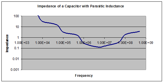
Figure 7 7 Impedance of a Capacitor with Parasitic Inductance
As it can be seen, the impedance is very high at low frequency. The capacitor is useless there. You will need to use your uncles 1000 µF capacitor in this region. This will keep him in business. At very high frequency also the impedance is high. We can not use this frequency for very high frequency.
But, in between these two frequencies, this capacitor is useful. It has a relatively low impedance in some range of frequency around the minima of the above curve. There is one frequency at which the impedance is lowest. This frequency is given by
Tom Ah, I am delighted to see this curve. Ok, so the left part of the curve says that my uncles 1000 µF capacitor manufacturing factory will not go out of business. I will now, no more ask questions about the low frequency range, otherwise you may change your mind during the discussion and my uncle will go out of business. That leaves the middle part of the curve and the right part of the curve. I will come to the right part of the curve later (there is obviously a concern as the impedance is high there). But first tell me the impedance is still high in the middle range. The lowest I see is still about 0.2 Ohm. You were telling that we need to achieve substantially lower impedance.
Bob Oh yes the impedance in the middle part of the curve is still high. But we can lower them. Do you know what is the inductance of two inductors is parallel ?
If L1 and L2 are two inductors connected in parallel, then their equivalent inductance L is given by
If there are n Inductors each of inductance L are connected in parallel, their equivalent inductance is given by
And you also know the if there are n Capacitors connected in parallel, their equivalent capacitance is given by
Now consider that instead of just one of these 0.1 µF capacitors we put n number of them. They are in parallel. Their equivalent capacitance becomes to , and their equivalent inductance becomes . So the equivalent inductance is given by
If there are 10 such 0.1 µF capacitors then the equivalent impedance will be one tenth of the impedance of one capacitor at ALL frequencies. If there are 100 such 0.1 µF capacitors then the equivalent impedance will be one hundredth of the impedance of one capacitor at ALL frequencies. What it means that the lowest impedance that you observed to be 0.2 Ohms will become 0.002 Ohms if we use 100 such capacitors.
The curve below shows the impedance of one capacitor versus impedance of 100 capacitors.
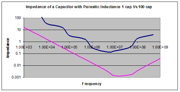 Figure 7 8 Impedance of a Capacitor with Parasitic Inductance comparison of 1 capacitor ( blue) impedance Vs. 100 capacitor impedance.
Tom Oh, now I understand why people use millions of 0.1 µF capacitors in designs. Now coming to the higher frequency part of the curve, I see that at frequencies in 500 MHz to 1 GHz range, the impedance is still high. How do we overcome that.
Bob At very high frequency, it is very difficult to get filtering using capacitors. You can get low impedance using low inductance capacitors and by increasing the number of capacitors. But even then there is a limitation. The traces and vias that connect the capacitors to the ground and power rail will have some inductance. This trace inductance will prevent achieving low impedance for high frequency near 1 GHz.
There is one way we can achieve low impedance near 1 GHz Using the capacitance between the power and ground plane. If the power and ground planes are adjacent to each other by a very thin dielectric, say 3 mils, then this acts as a capacitor with one good property it has very low inductance. With power and ground planes, it is possible to achieve low impedance at frequencies close to 1 GHz.
Tom OK, OK. Now I understand additional importance of ground and power plane. I had thought that the power and ground planes were only for ease of routing and for achieving desired characteristic impedances of the high speed traces on microstrip and stripline.
Now you had talked about low inductance capacitors. It looks like an interesting area for my uncles business. Can I ask my uncle to start business on low inductance capacitor. Can you tell me what kind of technology is there in it.
Bob Many companies are producing these low inductance capacitors. The trick is to place many capacitors in parallel. The resulting capacitor is called an array capacitor. By keeping the capacitors in parallel, their equivalent inductances reduce. These capacitors are more expensive than the normal capacitors. I do not have business sense, but you can ask your uncle to look into it. They do come expensive, so there should be some good margin in this product. You must however, note that the inductance of the mounting trace and mounting vias will not be reduced by the use of these magic capacitors. The sum total of the inductance of these capacitor and the mounting trace inductance must be compared against the sum total of the inductance of low cost capacitor and their mounting trace inductance. It turns out that the difference may not be that great. My thinking is the cost of these magic capacitors will be a deciding factor. If the cost of these magic capacitor is only marginally higher than the regular capacitor, then I will definitely use these magic capacitors.
Tom You talked about mounting trace inductance. But you did not take into account the mounting trace inductance when plotting the impedance for the capacitor.
Bob Yes I did not take into account the mounting trace inductance. Ideally, it should be taken into account. The mounting trace inductance is layout dependent. We should have traces that are as wide as possible and as small in length as possible to reduce the trace inductance.
You can take a typical value of the mounting trace inductance of the order of 0.2 nH. You should derate the capacitors inductance value to take into account the mounting inductance.
Tom You earlier told that the required impedance of a power supply system should be of the order of 0.01 Ohms. Where did you get this figure ? out of the air ? This is unscientific. How do we know the value of impedance required by a power supply voltage rail.
Bob- This 0.01 is a reasonable figure for typical embedded processor core supplies. It is slightly at higher end for IO supplies for the modern processor based designs. But, yes, there is a way to calculate the lowest ac impedance between power and ground planes required by a power supply system.
You must have known AC ripple, as you told in your first question that you observed some noise between the power and ground rails. Let us say ?V is the maximum allowed ripple in the power supply rail. If ?I is the maximum change in current, then the required impedance by the power supply system is given by
Z = dV/dI
As an example, consider a processor system that works on an IO voltage of 1.8V. The 1.8V is often used in mobile DDR IO. Most of the embedded processor to flash IC also use 1.8V. A typical requirement on this power supply is to have a maximum voltage ripple of 40 mV. A typical value of maximum change of current is 2 Amps.
The required impedance is given by
Z = dV/dV
or
Z = 40mV /2 Amps
or Z = 0.020 Ohms
Processor cores usually have more switching current requirement and tighter ripple voltage requirements, leading to required impedance of 0.01 ohms or lower.
Some errors have crept in on trying to put the book contents on website. Please look at the book for accurate information.
Previous - Bypass Cap - Power Supply Next - Differential Signal