Power Supply
All circuits and boards need a source of power to operate. The challenge is to provide a power supply which ensures an error free operation by way of supplying a stable and noiseless supply voltage across all ICs under all conditions.7.1 DC Perspective
A typical microprocessor based design has several DC voltages required by different sections of the circuit. The complete board has one power supply input and then there are several DC to DC converters to supply local power. The local powers may be for processor core, input output or PLL.
The traces going from the power supply to the actual power supply pins of the ICs have finite resistance. The non-zero PCB trace resistance results in DC drop. We are not considering any drop here due to the high speed of the signal or due to the inductive effect of the PCB trace. The voltage drop on the trace will depend upon two factors the resistance of the PCB trace and the current drawn by the circuit. As a PCB designer we can not control the current drawn by the circuit, but, we must estimate it using the datasheet of the ICs. We can however, control, to some extent, the PCB trace resistance.
The figure below shows a PCB trace having resistance R.
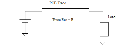
Figure Voltage drop on a PCB Trace
If I is the current flowing due to the load, the voltage drop across the trace is given by
V = IR [7 1]
The resistance of the PCB trace can be calculated using the formula
R = [6.787 x 10⁻⁷/(WT)] Ohms per inch [7 2]
where,
W = width of the trace in inches,
T = thickness of the trace in inches
For simplicity, the temperature dependent term has been removed and we are calculating the resistance at 20 deg C.
This gives us three simpler rules to minimize the voltage drop across the PCB trace
1. The width of the trace should be as wide as possible.
2. The length of the trace should be as small as possible.
3. The thickness of the trace should be as large as possible.
Once we calculate the PCB trace resistance, we must ensure that the voltage drop along the PCB trace is compensated by an increase in the source voltage. The example below illustrates it.
Example 7.1 - A microprocessor system needs 1.8V for its core. The trace from the power supply to the processor pins are 40 mils wide, 6 inch long and 0.5 mil thick. Assuming the current drawn by the processor to be 1A find the actual value of the voltage that should be generated at the source.
Solution The resistance of the 1 inch trace is given by the formula
R = [6.787 x 10⁻⁷/(WT)] Ohms per inch
= [6.787 x 10⁻⁷/(0.040* 0.005)] Ohms per inch
= 0.0034 Ohms per inch
The resistance of 6 inch trace is 0.0034 x 6 = 0.0206 Ohms
The voltage drop across the trace is 0.0206 Ohm x 1 A = 0.0206V
Therefore the source should generate a voltage of 1.8V + 0.0206V = 1.8206 V
Previous - Question and Answer - Chapter 6 Next - Power Supply AC perspective