Power Supply - AC perspective
Let us consider the following circuit where V1 represents the voltage source and L1 represents the inductance of the path delivering the voltage to the load Z.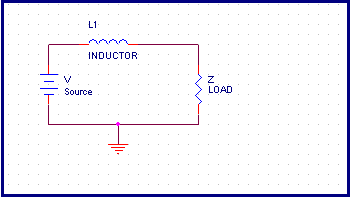
Figure 7.2 A Power Supply System
Let us assume a rapidly changing current flowing into the load Z. If the rate of the current change is dI/dt, there will be a drop of L*dI/dt across the inductance. The voltage available at the load will be
V1 = V L dI/dt [7.3]According to this equation, the inductance between the power supply source and the load will cause fluctuation in the supply voltage. To solve this problem we add a bypass decoupling capacitor as shown in the figure.
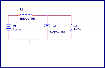
Figure 7.3 - A Bypass Capacitor to offset effect of Inductive trace
If the ac impedance of the capacitor C1 is low enough, the capacitor, the capacitor will provide the low impedance ac path for the noise.
Providing a low impedance ac path for the noise is central to the understanding of the design of noiseless power supply. The impedance of the capacitor is given by
Z = 1/(2 p fC) [7.4]
If the ac impedance is low enough, the ac signal will have very small value. Usually we need to provide voltage variation which is typically within 5% of the nominal power supply value. We can also supply absolute value of the voltage variation that the system can tolerate.
The above equation shows that, in order to have a low impedance we need the capacitance value as high as possible. This makes us believe the first intuitive choice a higher value of capacitance lowers the ac impedance more than a lower value capacitance and therefore is generally preferable.
Another factor that the above equation depends upon is the frequency. The equation says that we need a smaller value capacitor will work for higher frequency noises.
In the above equation, if we know the lowest required impedance, we can proceed to check for the required capacitor value.
The steps to calculate the value of the capacitor is very simple.
1. Get an estimate of the maximum change in load current.
2. Estimate the maximum allowable ripple in the power supply
3. Calculate the required impedance using dV/dI.
4. Find the value of the capacitor that will have impedance lower than the impedance calculated above.
We must provide a low impedance path across ALL the frequency ranges. A typical high speed PCB will need decoupling for frequency ranges typically from few MHz to 500 MHz and in some cases 1GHz.
To emphasize the points, look at the figure again. Z1 is the load that has a lot of input output switching. As a result of this there is a current flowing through the inductor L2. The drop across the inductor is given by 2pfL , where f represents the frequency of the ac signal or the power supply ripple. Consider the case when f is very small. There will be some drop in the voltage, leading to small ripple voltage appearing at load Z1. However voltage drop will be very small for very small frequencies. We do not need decoupling capacitors for small frequencies.
This voltage drop will also depend upon the inductance of the wiring that connects the power supply to the load. We need to find what is the frequency below which we can ignore this voltage drop.
The example below illustrates this point.
Example 7.2 - The power supply wiring of a power supply has an inductance of 100 nH. If the maximum change in the load current (dI) is 2A, and the tolerable ripple voltage is 50 mA, find the frequency below which there is no need of decoupling capacitor.
Solution Let f be the cut off frequency above which the ripple exceeds the 50mV value. The impedance of the power supply wiring is given by
ZL = 2pfL
The maximum impedance that can be tolerated is
= 50mV / 2A
= 0.025 ohm
This impedance of the power supply wiring must be lower than this impedance. The cut off frequency is given by
2pfL = dV/dI
= 0.025
f = 0.025 / 2pL
= 0.025/2p(100n)
= 3.98 MHz
When we say that below 3.98 MHz there is no need of decoupling capacitor, it does not mean there is no need of capacitor at all. We do not know at what frequency will the noise be generated. The above example only says that, if the noise happens to be of frequency below 3.98 MHz, the ripple will be less than 50 mV even if we do not use decoupling capacitor. Remember we are talking this only for very low frequency ripples or noises.
This also illustrates the fact that we should keep the inductance of the wire as small as possible. If these wires form part of the PCB, the wires should be as small as possible and as thick as possible. The value of 100nH is a reasonable value of the inductance using wires.
Previous - PS - DC Perspective Next - Inductance of Power Supply Wiring