Striline Differemtial Impedance
8.9 Stripline Differential impedanceThe differential impedance for a stripline is given by.
Zdiff = 2 x Z0 x (1-0.347e-2.9*D/B)
Zo = Single Ended impedance
D = separation between pairs of the plane
B = separation between reference planes
As seen from the formula when D decreases, while keeping B constant, Zdiff decrease. It actually depends upon the D/B ratio.
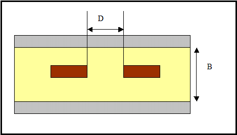
Figure 8.2 A differential stripline
The differential impedance of a stripline can be calculated using the online calculator at
http://www.referencedesigner.com/tutorials/si/si_11.php
8.10 Crosstalk in Differential Signaling
Let us take a look at look at a differential signal routing in which the trace width of the differential signals D+ and D- is 5 mils each and they are separated by 5 mils. It is possible that an aggressor such as the one shown has to pass close to the differential traces. The aggressor in that case is closer to the trace D- than to the trace D+. If the gap between the aggressor and the D- signal is say 5 mils, then the separation between the aggressor and the D+ trace will be 15 mils. The aggressor is at thrice the distance from D+ than from D-. The cross talk introduced by the aggressor on D- is substantially more than that of on D+. This does not get cancelled when it reaches the receiver.
To overcome this problem we have few choices. We can restrict only slow edge rate signals to come near the differential traces. If we route non fast rising edge signals, for example I2C bus, close to the differential bus, it will utilize the board area more efficiently without creating the crosstalk problem. Another choice is to force the high speed signals to stay away from the differential signal as much as possible. A separation of at least 3x , where x is the separation between the positive and negative number, is a good choice.
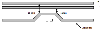
Figure 8.3 - The aggressor very close to a differential pair.
Previous - Differential Impedance Next - HyperTransport - Case study