2.3 Adding Delay Intentionally
CHAPTER 22.3 Adding Delay Intentionally
It is often desirable to add or reduce delay to a clock line with respect to a data line to improve the timing margins. In such case, instead or purposely minimizing skew, we change our objective to add additional delay in the clock line with respect to the data line. To be able to do this we must have a good understanding of the set up and hold timing models of the receiver section of the circuit. We should also have an understanding of the timing relationship at the driver side. If the simulation shows an improvement in the timing margin by use of clock or data line delay adjustment, we can implement it at the PCB design level.
Fixed delay using the transmission line is the most common form of providing delay at the PCB design level. There is no extra cost involved and it often easy to implement. The drawback of this scheme is that it needs space. At propagation speed of 150 ps per inch, providing 600 ps of delay will need 4 inch of extra length.
The figure below shows a serpentine delay. The spacing between the delay lines is very close.
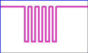
Figure 2.2 A serpentine routing to add intentional delay. Note that the traces are too close
If the adjacent traces in the serpentine delay are very close to each other, there is a coupling between the traces. This in turn provides an ac return path. As a result, the signal travels faster in the serpentine path as compared to the straight path. The effective delay of the serpentine delay is therefore smaller than the corresponding straight trace delay.
If you space the traces in serpentine delay lines too far away, the coupling is reduced and the signal speed is close to that of the straight trace. However, it takes too much of PCB space. Keeping the serpentine trace too close has two undesirable effects. The first is the reduction in the effective delay. The second is distortion in the signal. A signal after traveling through a serpentine trace shows plateau at the low and the high levels of the signal. The plateau at the low level can eat up voltage margin.
We must therefore simulate the serpentine traces to take into account the reduction in the effective delay and creation of voltage plateau.
Previous - Integrity of Point to Point Signal Next - Coupling of Traces