Periodic Waves and Fourier Transform
CHAPTER 11.8 Periodic Waves and Fourier Transform
A perfectly sinusoidal clock or signal seldom happens in real world. We encounter square waves, sawtooth waves, deteriorated square waves. Cycle after cycle, these waves repeat the same pattern. In other words, the instantaneous value of these waves is same after some fixed amount of period. These waveforms are called periodic waves. The fixed amount of time after which the signal repeats is called period of the wave.
A periodic waveform consists of one lowest frequency component and multiples of the lowest frequency component. The lowest frequency component is called fundamental and the components that are multiples of fundamental frequency are called harmonics.
French mathematician Jean-Baptiste Joseph Fourier demonstrated that any periodic waveform is composed of a fixed term, plus an infinite series of cosine terms, plus an infinite series of sine term. The frequency of these infinite sine and cosine terms are multiples of the one fundamental frequency.
Mathematically we represent this statement as
f(t) = A0+A1cos?t + A2cos2?t + A3cos3?t + - - - - - - + Ancos n?t
+A1sin?t + A2sin2?t + A3sin3?t + - - - - - - + Ansin n?t [1 2]
A0 represents the DC component of the periodic wave. For most periodic waves, the values of the coefficients of the cosine and the sine terms diminish rapidly as the order of the harmonics increases.
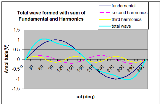
The figure below illustrates a periodic wave (named total wave) formed of a perfect sine wave of amplitude 1, a second harmonics of amplitude 0.2, and a third harmonics of amplitude 0.15

Figure 1 3: A periodic wave composed from sum of the fundamental, 2nd Harmonics and 3rd Harmonics
By varying the relative amplitudes of the fundamental and harmonics we can get more and more shapes.
You may now notice that the rising edge of total waveform in the above diagram is faster than the rising edge of fundamental sine wave. This is because all the harmonics start rising at the same time in this case. In order to preserve a higher rising edge signal and its shape we will need to preserve more harmonics of the wave as it propagates. In other words, it will require more bandwidth.
A symmetrical square wave is composed of the fundamental wave and the odd harmonics of sine waves. The amplitude of the harmonics is inversely proportional to the frequency.
f(t) = A[sin?t + (1/3) sin3?t + (1/5) sin5?t + - - - - - - + (1/n)sin n?t] [1.3]
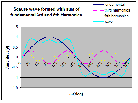
The figure below shows the waveform produces by taking into account the fundamental, the first harmonics and the third harmonics into account. Notice that the rise time of the square wave is faster than the fundamental and the harmonics. The ripples of the wave would have decreased had we taken more harmonics.

Figure 1 4: A square wave formed with fundamental, 3rd harmonics and 5th harmonics.
The square wave in the figure above (marked wave) is not a perfect square wave. Why? Because we have formed it with only up to fifth harmonics. If we take more and more harmonics (7th , 9th etc.) and add them, the resulting wave will be more and more close to a perfect square wave.
What does it practically imply? If we have perfect or a near perfect square wave that we want to propagate through a, say, PCB trace without any distortion, we will need to pass more and more harmonics of the wave distortion less. If up to 5th harmonics are passed without distortion, final resulting wave will have some distortion. If we can pass up to 7th harmonics without distortion, the resulting wave will have smaller distortion.
Practically, as the frequency increases, the channel or the PCB trace attenuates, distorts the signal more. This results in a final signal that is not a perfect replica of the original signal. If the PCB traces would have attenuated all the frequencies equally, the signal, after passing through the trace will preserve exact shape but only with reduced amplitude. However, as the higher frequencies are attenuated more than the lower frequencies, the signal gets distorted.
Example 1-1 – Find the 10 to 90 % rise time of a perfect sine wave of Amplitude A, and frequency f.
Solution – A sine wave with frequency f and amplitude A is given by
A(t) = Asin2p ft
If A1(t) and A2(t) represent 10% and 90% amplitudes at t = -T and t = +T, then
the rise time is given by t = 2T.
A1(t) = Asin2p ft1
A2(t) = Asin2p ft2
A2(t) – A1(t) = Asin2p ft2 - Asin2p ft1
0.8A = A(sin2p ft2 - sin2p ft1)
0.8 = sin2p fT - sin2p f(-T)
0.80 = 2sin2p fT
0.40 = sin2p fT
2p fT = sin-1(0.45) = 0.411
2T = 0.11 / f
The rise time of a sine wave is 0.14/ f
If your wave is a perfect sine wave, with no harmonics, its bandwidth requirement to preserve the signal shape is low.
Practical digital signals are seldom perfect sine waves. In fact, these are more likely to be close to a square wave with a fast rising edge. This will mean that they can thought to be made up of higher harmonics with significant values of the coefficients of higher harmonic components. To ensure that this signal stays undistorted will mean that the channel or the PCB trace should preserve not only the fundamental frequency of the wave but also its harmonics. Many things start changing as the frequency starts going up. The inductive and capacitive effects of small traces, vias, package pins become substantially significant if we start crossing the frequency higher than 100 MHz.
Previous - Knee Frequency Next - Tom and Bob, Chapter 1