EMI Case Study
Making a faraday cage for EMI testing and installing necessary equipments including spectrum analyzers and antenna is an expensive exercise. It is beyond the budget of most small to medium size companies, not only because of the one time equipment cost but also in terms of expense involved in hiring required EMI personal who has enough expertise to calibrate the equipments and antenna and run the tests. Moreover, if we do not have enough products rolling out the investment on the EMI lab sits idle. If your company is big enough to roll out one product every week, the investment is worth it.
In the absence of the equipment and expertise how do you conduct and test your equipments ? There is one simple solution. Take appointment for half a day to any of the EMI laboratory. They charge some fees for it. Have them run one simple EMI test to get a feel of worst case emission. The EMI test engineer will run the test with antenna polarized in horizontal, vertical and rotating positions. He will capture the worst case scenario. He will be able to tell you if the test is likely to pass and how much is the margin. If the test is likely to fail he should be able to tell the frequencies where the test is likely to fail. Note down these frequencies very carefully. Also note down the number of dBs by which you are failing the EMI for each of the frequencies involved. If he can give you a print out of the graph showing frequencies where your equipment fails, take the print out.
Bring your product back to your lab. You need some simple instruments. One of the things that you definitely need is a Spectrum Analyzer. You do not need a 20 GHz spectrum analyzer. Just a 2 to 3 GHz should be good enough. You also need EMI Probes. I have in my lab an old Tektronix Spectrum Analyzer, part number 496P. At 1.8 GHz it is not a fancy spectrum analyzer. It does not have digital storage capability. But it works. I also have two Anritsu EMI probes with part number MA2610B and MA2610C. The EMI probe kit also comes with MH648A RF amplifier kit that has a rated gain of 30 dB. You may search some similar items.
When the report from the lab is in my hand I carefully noted down the frequencies that were failing. In the report, I found three fundamental frequencies that seemed to fail by margins ranging from 4 dB to 10 dB. The lowest frequency that it is failing was 600 KHz. There was one at 50 MHz and its third harmonics at 150 MHz. Then there was 133 MHz and its third harmonics.
The board was energized in the lab. The Spectrum analyzer was connected and the EMI probe was hooked. I started looking for source of 600 KHz emission. After a few hit and trial it seemed to be coming from switching power supply. I had used the national semiconductor LM2717-ADJ IC for my switching regulator. The switching frequency of the power supply was 600 KHz. This 600 KHz frequency also modulated the 133 MHz frequency. The peak ripple of the 600 KHz frequency was making the emission worse. Fortunately there was an easy solution. The resistance connected to Pin 19 of LM2717-ADJ was changed from 22.1K to 46.4K thus reducing the switching frequency to 300 KHz . This solved the 600 KHz related emission problems. The clocks of 50 MHz and 66 MHz were sources of failure at their third harmonics. Changing series resistors and adding capacitors to slow down the edges did not yield the desired reduction in emission. We also tried putting a faraday cage around the oscillator. It did not reduce to the desired level. Reducing the power supply voltage to the oscillator from 3.3V to 2.5V seemed to help a bit. In the end all the efforts did reduce the emission significantly. But the board was barely passing the EMI test. A dithering oscillator was finally used to have the system passed. The manager was happy. There was party and celebration when I came back from the EMI lab announcing that the system passed EMI test. I was not very happy. It was not a perfect solution. It was not an engineers delight. But it worked for now.
The short story is - explore the emission levels as soon as the board is up and running. After testing a few boards with a spectrum analyzer and probe you will have a feel of the level of emission that is more likely to fail. You are not concerned with the absolute level of emission. You only need to find the relative value. And once the value you observed with probe and spectrum analyzer system is close to failing value you need to do something about it.
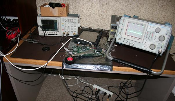
Figure - A setup like this using an Spectrum Analyzer and a Probe can catch EMI issues early.
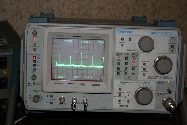
Figure - Spectrum Analyzer showing emissions
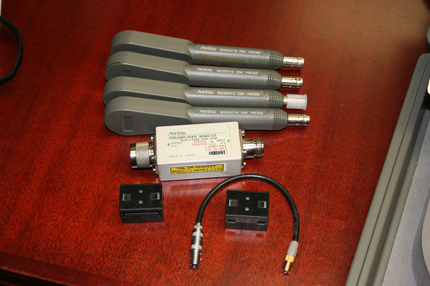
Figure - EMI Probe Kit
Previous Next