High Speed Characterization - Jitter
An ideal signal is represented by a trapezoid as shown in the figure below. The trapezoid has a clean 0 level at voltage level of 0 volts, has a clean l level corresponding to a high voltage level and there is a finite rise time associated with the rise of the signal from 0 to 1.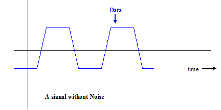
Figure - Ideal Signal
When this signal is transmitted to a channel and received a number of sources add noise to this signal. This source of noise can be at the transmitter or at the channel or can be resulted from reflections and mismatch. This undesired signal is added to the ideal signal. In the presence of the noise, this noise signal gets added to the original signal resulting in a signal that looks similar to the signal shown below.
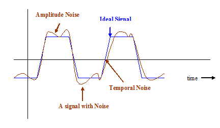
Figure - Signal with noise
There are two effects that the noise causes to the signal. The first effect is that it causes the amplitude of the signal to deviate from its nominal value. The second effect is that it causes the signal to deviate from its nominal value in the time domain. This second effect is called the jitter. Simply put, jitter is noise in time domain.
How Jitter causes Bit Error Rate (BER) Bit error rate is defined as the ratio of the number of error bits received with the total number of bits received.
BER = Ne /N
Where Ne= number of bits received with error
N = total number of bits received.
The receiver of any communication channel samples the received bit. It then takes a decision by comparing the voltage with a reference voltage. A jitter as in the figure above may mean that the voltage level of the signal may remain too low at the point to sampling to be observed as a high signal This causes a jitter error.
Previous Next