Guard Traces
A guard trace reduces the cross talk by coupling the electromagnetic waves to the guard trace instead of coupling to the nearby victim trace. To insert a guard trace there must be enough space between the traces. In a typical PCB, the minimum trace width allowed is 4 mils and the minimum trace separation allowed is 4 mils. In order to insert a guard trace, the edge to edge separation between the traces needs to be at least 12 mils. In many cases, a separation is good enough to reduce the crosstalk. If the power plane is not too distant from the signal traces, the cross talk may be low enough with 12 mil seperation not to require guard traces.
There are however cases where signals routed on the microstrip are still susceptible to cross talk and additional protection is needed. Guard traces can be used under such condition to further reduce the amount of the cross talk.
We will consider here a typical practical scenario for crosstalk in a microstrip. Consider the case where two traces are separated by 12 mils.
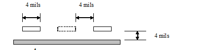
Figure - A typical guard trace insertion
We consider first the cross talk created by two traces separated edge to edge by 12 mils. The hspice code U-Element is shown below.
* NEXT Crosstalk - Microstrip
.Tran 50ps 4ns
.OPTION Post NoMod Accurate Probe Method=Gear
VIN 1 0 PWL 0 0v 50ps 0v 350ps 2v
RG 1 2 60
U1 2  6  0 3  7 0 USTRIP L=2000mils
R2 3 0 60
R3 7 0 60

.Model USTRIP U LEVEL=3 PLev=1 Elev=1 Dlev=1 Nl=2 Ht=4mils
+ Wd=4mils Th=1mils Sp=12mils  Kd=4.4

.Probe v(1) v(6)
.End
When we run this simulation and observe the signal at v(6), it shows a maximum backward cross talk of 0.060V.
We now insert a guard trace. We have however, not grounded the guard trace. The hspice code is shown below. The U element now has 3 traces. The middle trace between node 4 and 5 is guard trace.
* NEXT Crosstalk Microstrip
.Tran 50ps 4ns
.OPTION Post NoMod Accurate Probe Method=Gear
VIN 1 0 PWL 0 0v 50ps 0v 350ps 2v
RG 1 2 60
U1 2 4 6 0 3 5 7 0 USTRIP L=2000mils
R2 3 0 60
R3 7 0 60
.Model USTRIP U LEVEL=3 PLev=1 Elev=1 Dlev=1 Nl=3 Ht=4mils
+ Wd=4mils Th=1mils Sp=4mils Kd=4.4
.Probe v(1) v(6)
.End
When we run this simulation and observe the signal at v(6), it shows a maximum backward cross talk of 0.0492V. The crosstalk does reduces.
We now connect the two ends of the guard trace with ground. The hspice code is shown below.
* NEXT Crosstalk - Microstrip
.Tran 50ps 4ns
.OPTION Post NoMod Accurate Probe Method=Gear
VIN 1 0 PWL 0 0v 50ps 0v 350ps 2v
RG 1 2 60
U1 2 4 6  0 3 5 7 0 USTRIP L=2000mils
R2 3 0 60
R3 7 0 60

Rx 4 0 0
Ry 5 0 0

.Model USTRIP U LEVEL=3 PLev=1 Elev=1 Dlev=1 Nl=3 Ht=4mils
+ Wd=4mils Th=1mils Sp=4mils  Kd=4.4

.Probe v(1) v(6)
.End
When we run this simulation and observe the signal at v(6), it shows a maximum backward cross talk of 0.0197V.
To understand the code better a diagram showing the microstrip transmission line and the node numbers produced here.
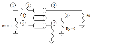
Figure -A crosstalk example net with guard traces connected to ground.
Practical Considerations for routing Guard Traces
It is clear that guard traces provide at least some definite theoretical advantage. Practically, the guard traces need space between the traces. By reducing the space between the traces, we reduce the amount of the crosstalk anyway. Guard traces do not help when we need them most. We need some method to reduce the cross talk when the traces are close by. Unfortunately guard traces do not help here.
The requirement is exacerbated by the requirement that the guard traces must be connected to the ground layer to be more effective. What this will mean is that, we need to add vias, at least at the ends of the guard traces. Adding vias take up a space of at least 8 mils. This means that we need a some more space between the traces to insert the vias. Practically insertion of guard traces with ground vias makes the things even more difficult from the perspective of designing a dense PCB board.
There is not doubt that the guard traces, if implemented will can result in lower cross talk and improve the system margin. This scheme is practical if the number of traces running in parallel is small. If the number of traces running in parallel is large, we may like to insert guard traces only for the critical nets. As an example take the case of routing DDR Bus. We consider here the DDR for the server products that has error detection capability. If there is any error in the Data Bus, it can be detected by the system. An error in the DQS or the address bus, however, can be disastrous. The DQS and Address Lines are therefore, most important ones and must be protected from the cross talk. These lines are therefore routed on inner layers. If we have to route these nets on outer layers, we may think of inserting guard traces for the critical traces.
Analog signals often are more sensitive to the crosstalk, in terms of final results. The analog signal do not run like a bus, and, it may be a good idea to put guard traces next to the critical analog signals.
For the same reason, a ground flood on the external layer can not only reduce cross talk but may also reduce electromagnetic radiation by way of coupling the signals to the nearby ground traces.
Previous Next