Near Ned Crosstalk Microstrip Vs stripline
We just concluded that a stripline that has power planes farther from the traces generate more cross talk. When the power planes are close to the traces, the electromagnetic fields stay close to the trace and the power planes, leading to smaller coupling in nearby trace. When the power planes are farther apart the electromagnetic fields have larger roundabout area. The nearby traces, therefore see more electromagnetic field because of the aggressor. This causes more cross talk. We can extent this analogy to conclude that there will be more cross talk in coupled traces in case of microstrip than in case of stripline. The one side of the Microstrip does not has power plane, leading to more roundabout dispersion of the electromagnetic waves. This leads to more cross talk in coupled traces in case of microstrip.
Let us try some simulations to compare microstrip versus stripline crosstalk. We want to keep parameters close, so as to make an apple to apple comparison. We will keep the separation between the traces same in case of stripline and microstrip, 4 mils each. We will also keep the separation between the trace plane and the power plane 6 mils in case of microstrip. We will also keep the separation between the trace layer and the two power planes of the stripline 6 mils each.
The only difference between the microstrip and the stripline structure is the trace width. We allow this variation, in order to match the impedance. The trace width is not expected to make difference in the cross talk. The impedance for the microstrip structure with 6 mils trace width, 6 mils separation to ground plane and Er of 4.4 gives and impedance of 65 ohm according to quick calculations using formula method in
http://referencedesigner.com/tutorials/si/si_06.php
The hspice code that can be used to calculate the crosstalk is shown below.
* NEXT Crosstalk Microstrip
.Tran 50ps 4ns
.OPTION Post NoMod Accurate Probe Method=Gear
VIN 1 0 PWL 0 0v 50ps 0v 350ps 2v
RG 1 2 50
U1 3 2 0 5 6 0 USTRIP L=2000mils
R2 5 0 50
R3 6 0 50
.Model USTRIP U LEVEL=3 PLev=1 Elev=1 Dlev=1 Nl=2 Ht=6mils
+ Wd=6mils Th=1mils Sp=4mils Kd=4.4
.Probe v(1) v(3) v(5)
.End
Simulation using this code produces the following NEXT waveform in microstrip.
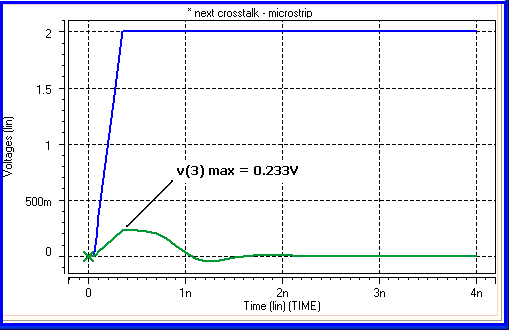
Figure 11 7 - Crosstalk in microstrip
The near end crosstalk in this case of microstrip is 0.233 V.
Let us now perform the same experiment with stripline. The hspice code for simulation for the stripline case is as follows
* NEXT-stripline
.Tran 50ps 4ns
.OPTION Post NoMod Accurate Probe Method=Gear
VIN 1 0 PWL 0 0v 50ps 0v 350ps 2v
RG 1 2 50
U1 3 2  0 5 6  0 USTRIP L=2000mils
R2 5 0 50
R3 6 0 50

.Model USTRIP U LEVEL=3 PLev=1 Elev=1 Dlev=2 Nl=2 Ht=6mils
+ Wd=6mils Th=1mils Sp=4mils Ts=13mils Kd=4.4

.Probe v(1) v(3) v(5)
.End
This structure produces a cross talk of 0.138V. We therefore conclude that the microstrip structure produces significantly more crosstalk than a similar stripline structure.
I would like to remind that we have been discussing near end cross talk so far. The near end crosstalk level gets saturated when the length of the parallel overlap exceeds half the rise time of the aggressor signal.
Most of these methods to contain near end cross talk applies to the far end cross talk level. In simulations we however, need to keep in mind that the level of the far end cross talk keeps increasing with the length of parallel overlap.
Previous Next