Crosstalk due to Capacitive coupling
Directionality of CrosstalkLet us assume that the trace X in the figure below carries a signal propagating in the direction from A to B. Trace Y is a nearby trace in which crosstalk in introduced by a fast rising edge on trace X. The trace X is called aggressor and trace Y is called victim when analyzing the cross talk. The cross talk introduced from trace X to trace Y starts propagating in two directions simultaneously. The backward cross talk or Near End Cross Talk (NEXT) is observed on the victim line at the end nearest to the driver line of the aggressor. The forward cross talk or Far End Cross Talk (FEXT) is observed on the victim line at the end farthest from driver of the aggressor.
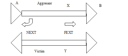
Figure Directionality of Crosstalk
Near End Cross talk
When the traces running in parallel has zero length of parallelism, there is no cross talk, forward or the reverse. As the length of the parallelism is increased the amplitude of the reverse cross talk increases in proportional to the length of the parallelism. This increase in amplitude continues till the delay corresponding to the length of parallelism is one half the rise time of the incident signal. After that, the amplitude of the reverse crosstalk stays constant and does not increase with the increase in the length of parallel overlap. Increasing the length of parallel overlap increases the duration of the reverse crosstalk pulse and not its amplitude.
Let us take a look at some simulation results to see the NEXT waveforms and its dependence on various parameters. The hspice code to using a U-element is shown below.
* Stripline circuit Near End Cross Talk
.Tran 50ps 5ns sweep length 500mils 2500mils 500mils
.OPTION Post NoMod Accurate Probe Method=Gear
VIN 1 0 PWL 0 0v 50ps 0v 350ps 2v
RG 1 2 50
U1 3 2  0 5 6  0 USTRIP L=length
R2 5 0 50
R3 6 0 50

.Model USTRIP U LEVEL=3 PLev=1 Elev=1 Dlev=2 Nl=2 Ht=15mils
+ Wd=12mils Th=1mils Sp=4mils Ts=31mils Kd=4.4

.Probe v(1) v(3) v(5)
.End
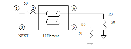
Figure - Near End Cross Talk Simulation
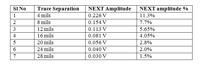
This code is for a stripline with two traces of width 12 mils each separated by a distance of 4 mils. The two power planes on the two sides of the traces are at 15 mils. This makes the characteristic impedance of the lines 50 Ohms. Both the lines are terminated with 50 Ohms. We send a step signal on one of the traces with a rise time of 300 ps. At 150 ps per inch the equivalent length on PCB of the corresponding to this rise time is 2 inch. Half of this length is 1 inch. The NEXT waveform produced with this code is shown below.
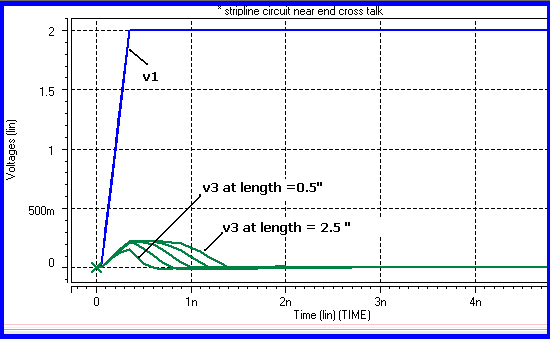
NEXT simulation variation with parallel overlap length
As the length of the trace is increased from 0.5 inch to 1 inch, the amplitude of the NEXT increases. At 1 inch, the time equivalent to the length of the trace is roughly half the rise time of the incident signal. Any further increase in the length of trace does not increase the amplitude of the NEXT signal. However, the width of the NEXT signal increases with the further increase in the trace length.
The maximum of the NEXT signal in this case is about 0.226 V or roughly 11% of the incident signal.
Effect of Trace separation on NEXT signal amplitude
In the preceding simulation, we placed the traces separated at 4 mils. This is almost the closest distance that traces can be placed in a standard PCB. One way to reduce the cross talk is to increase the separation between the traces. Let us try to run the simulation for 2 inch of trace length for different values of trace separation. At this length the amplitude of the NEXT signal saturates.
* Stripline circuit NEXT - effect of seperation
.Tran 50ps 5ns sweep separation 4mils 16mils 4mils
.OPTION Post NoMod Accurate Probe Method=Gear
VIN 1 0 PWL 0 0v 50ps 0v 350ps 2v
RG 1 2 50
U1 3 2  0 5 6  0 USTRIP L=2000mils
R2 5 0 50
R3 6 0 50

.Model USTRIP U LEVEL=3 PLev=1 Elev=1 Dlev=2 Nl=2 Ht=15mils
+ Wd=12mils Th=1mils Sp=separation Ts=31mils Kd=4.4

.Probe v(1) v(3) v(5)
.End
The table below shows the measured amplitude of the signal as a function of separation between traces. Note that the separation between the traces is defined according to the U-Model of the hspice, which means the edge to edge separation between the traces, rather than the center to center spacing.
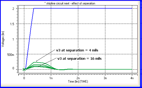
Figure Effect of separation between traces on NEXT The table below summarize the NEXT amplitude level as a function of the trace separation. Increasing the separation to 20 mils decreases the NEXT amplitude to 2.8%.
Table - Variation of NEXT amplitude as a function of trace separation
The above simulation results are for the case when the victim trace is not terminated at all. There is no resistance connecting the node 3 to the ground or a voltage source. As a result there is a reflection from the node 3 and the amplitude of the reflection shown is double the amount. If we want, we can terminate the victim source as shown in the figure below.
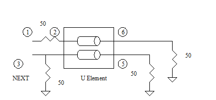
Figure Terminating the victim trace at source end.
The following spice code simulates the above conditions.
* Stripline circuit NEXT - victim terminated at source
.Tran 50ps 5ns sweep separation 4mils 16mils 4mils
.OPTION Post NoMod Accurate Probe Method=Gear
VIN 1 0 PWL 0 0v 50ps 0v 350ps 2v
RG 1 2 50
Rs 3 0 50
U1 3 2  0 5 6  0 USTRIP L=2000mils
R2 5 0 50
R3 6 0 50

.Model USTRIP U LEVEL=3 PLev=1 Elev=1 Dlev=2 Nl=2 Ht=15mils
+ Wd=12mils Th=1mils Sp=separation Ts=31mils Kd=4.4

.Probe v(1) v(3) v(5)
.End
Table - Variation of NEXT amplitude as a function of trace separation with victim terminated with 50 Ohms at source
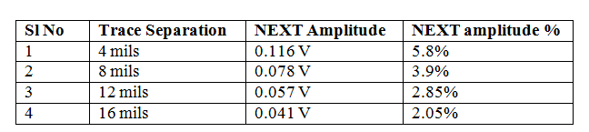
The source end termination in the victim signal has one positive effect. The backward crosstalk, gets terminated when it reaches the node at the source. It does not get reflected further. Had there been no termination, it will reflect from there and continue to move towards the victim destination which will further degrade the signal at the victim receiver.
The above simulation and the results are only for two traces. The Near End Cross talk will be worse, if there are more than two or more traces in the vicinity of the victim trace. Usually, the worst case cross talk is calculated by placing a total of 4 aggressors, two on the left and two on the right of the victim trace. Practically such cross talk is generated from the software by sending a pattern of 0s and 1s which will make the 4 aggressors rise and fall at the same time.
In hspice, the 4 aggressor and 1 victim case can be simulated using 5 element U-Model. The hspice code below will simulate 5 traces with one of them as victim and other 4 as aggressor.
* Stripline circuit NEXT - 4 aggressors
.Tran 50ps 4ns
.OPTION Post NoMod Accurate Probe Method=Gear
VIN1 2 0 PWL 0 0v 50ps 0v 350ps 2v
VIN2 3 0 PWL 0 0v 50ps 0v 350ps 2v
VIN3 5 0 PWL 0 0v 50ps 0v 350ps 2v
VIN4 6 0 PWL 0 0v 50ps 0v 350ps 2v

R1 2 7 50
R2 3 8 50
R3 5 9 50
R4 6 10 50

U1 7 8 11 9 10 0 12 13 14 15 16 0 USTRIP L=2000mils

R5 12 0 50
R6 13 0 50
R7 14 0 50
R8 15 0 50
R9 16 0 50

.Model USTRIP U LEVEL=3 PLev=1 Elev=1 Dlev=2 Nl=5 Ht=15mils
+ Wd=12mils Th=1mils Sp=4mils Ts=31mils Kd=4.4

.Probe v(2) v(11)
.End
If we run this hspice code, we get a NEXT cross talk level of 0.494. The NEXT amplitude from the two aggressors next to the victim at a separation of 4 mils is 0.226V each. The two aggressors farther from the victim at a separation of 20 mils ( 4 mils gap + 12 mils trace width + 4 mils separation) is 0.056V each according to the table below. The total NEXT amplitude is slightly less than the sum of the crosstalk amplitudes due to the four aggressors.
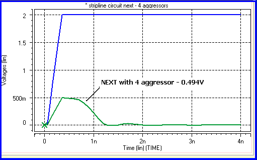
Figure NEXT with 4 aggressors
In general a 3 trace analysis with one victim and two aggressors should give a fairly good idea of the cross talk level. A 5 trace analysis with one victim and 4 aggressors should be done to get a more accurate result. The cross talk level falls rapidly with distance and using 6 or more aggressors will not create much difference due to cross talk alone. Practical scenario is, however different. Switching all but the victim signal of a 32 bit wide data bus can generate the SSO noise in addition to the crosstalk. The combined effect is the failure of the bus when this pattern is generated from the software.
Effect of separation from Power Planes
We will now create some symmetrical stripline structures, each with a characteristic impedance of 50 Ohms and see how the NEXT varies by decreasing the separation between the traces and the nearest plane.
Here are some structures that gives 50 Ohms ( using quick calculation from http://www.ideaconsulting.com/strip.htm)
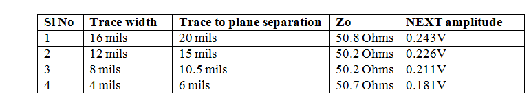
Case 1 : Trace width = 16 mils, trace to plane separation = 20 mils , Er = 4.4, Trace thickness = 1 mil, Zo = 50.8
Case 2 : Trace width = 12 mils, trace to plane separation = 15 mils , Er = 4.4, Trace thickness = 1 mil, Zo = 50.2
Case 3 : Trace width = 8 mils, trace to plane separation = 10.5, Er = 4.4, Trace thickness = 1 mil, Zo = 50.2
Case 4 : Trace width = 4 mils, trace to plane separation = 6, Er = 4.4, Trace thickness = 1 mil, Zo = 50.7
We keep the length of parallelism 2 inches in all the four cases. The traces are separated 4 mils edge to edge in all four cases. The table below lists the NEXT amplitude level for all the four cases.
Table Variation of NEXT amplitude with trace to plane separation
The following hspice code was used to generate the amplitude of the NEXT pulse. The NEXT pulse was measured using probe on net v(3).
Four U-Element models were used. Three of them have been commented. By successively using the U-Elements we can generate the NEXT waveform and measure the amplitude.
* NEXT-variation with plane separation
.Tran 50ps 4ns
.OPTION Post NoMod Accurate Probe Method=Gear
VIN 1 0 PWL 0 0v 50ps 0v 350ps 2v
RG 1 2 50
U1 3 2  0 5 6  0 USTRIP L=2000mils
R2 5 0 50
R3 6 0 50
* 4 mils wide trace, 6 mils separation from plane

.Model USTRIP U LEVEL=3 PLev=1 Elev=1 Dlev=2 Nl=2 Ht=6mils
+ Wd=4mils Th=1mils Sp=4mils Ts=13mils Kd=4.4

* 8 mils wide trace, 10.5 mils separation from plane

*.Model USTRIP U LEVEL=3 PLev=1 Elev=1 Dlev=2 Nl=2 Ht=10.5mils
*+ Wd=8mils Th=1mils Sp=4mils Ts=22mils Kd=4.4

* 12 mils wide trace, 15 mils separation from plane

*.Model USTRIP U LEVEL=3 PLev=1 Elev=1 Dlev=2 Nl=2 Ht=15mils
*+ Wd=12mils Th=1mils Sp=4mils Ts=31mils Kd=4.4
* 16 mils wide trace, 20 mils separation from plane

*.Model USTRIP U LEVEL=3 PLev=1 Elev=1 Dlev=2 Nl=2 Ht=20mils
*+ Wd=16mils Th=1mils Sp=4mils Ts=41mils Kd=4.4

.Probe v(1) v(3) v(5)
.End
The purpose of including the hspice code is to enable independent verification from other source. It is possible that someone else may be running some simulation tool other than hspice. If that happens he or she may find the results at a variation from the one stated above. If that happens he or she should be able to find the assumptions behind the simulations. It will also enable me to spot any inaccuracy in my simulations with a possibility of correcting the results in future edition of the book.
The result of this simulation shows that the NEXT crosstalk can be reduced by reducing the separation between the signal and the power plane. This is a very important result. It is more important than the conclusion that increasing the separation between the traces reduces NEXT cross talk. Even though increasing the separation between the traces have more dramatic effect on the reduction of crosstalk, this option is not available many times. PCB sizes are shrinking and PCB designers have to keep the traces very close by in order to route all the traces. As a result, the only option is to reduce the trace to ground separation and reduce the trace width accordingly to achieve the required impedance.
Previous Next