Inductance
CHAPTER 55 Inductance
5.6 Mutual Inductance
So far we have been discussing the magnetic field line loops generated by an isolated wire. Let us now assume that there are two wires spaced close by as shown in the figure below.
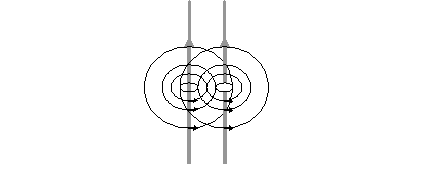
Figure 5 1 - Origin of Mutual Inductance.
Let us consider the effect of the current flowing in the second wire on the first wire. For now assume that there is no flow of current in the first wire. The current flowing in the second wire, generates magnetic lines of loop. Some of these magnetic loop lines encircle the first wire. If we bring the second wire close to the first wire, the number of magnetic lines of loops encircling the first wire will increase. If we increase the current in the second wire, the number of magnetic lines of loop encircling the first wire will increase.
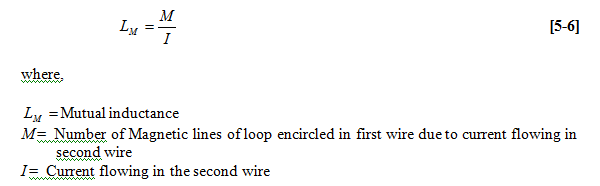
To measure the effect of current carried in the nearby wire on the first wire we define the term mutual inductance. Make 1 ampere of current flow in the second wire and find the number of magnetic lines of loop in the first wire. This number will be called mutual inductance.
If there are M magnetic lines of loop encircled in the first wire due to a current I flowing in the first wire, the mutual inductance is defined as
5.7 Changing Magnetic Field and Induced EMF
We will now state the Faradays law of electromagnetic Induction. It says that if the number of magnetic lines of loops across an inductor changes, it induces a voltage across it.
If the number of magnetic lines of loop changes by ?N in a time period of ?t, the voltage induced across the inductor is given by,
V = ?N /?t
[5 7] where,
V = voltage induced across the inductor.
?N = Change in the number of magnetic lines of loop
?t = time duration of the change of number of magnetic lines of loop
It is this induced voltage that creates the signal integrity issues.
There are two ways the number of magnetic lines of loop around a wire may change. The first is when the current in the wire itself change. A second way the number of magnetic lines of loop could change is when the current in the nearby wire changes.
For now let us focus again of a single wire. If the current in the wire changes, there will be a change in the number of magnetic lines of loop encircling the wire. If the current flowing in the wire changes by amount ?I, and if it leads to a change in the number of lines of loop by ?N, then
?N = L?I
Substituting this in the equation above leads,
[5 8] V = L?I/?t
We therefore see that the voltage induced in a single wire will be high if the inductance of the wire is high. The induced voltage will be high if the rate of change of current is high.
5.8 Total Inductance
Till now we have been discussing the magnetic field produced by an isolated wire carrying current I. We had assumed that a current I enters into the wire and comes out of it. Let us think of a practical scenario. The current entering into the wire will return somewhere. If it is a ribbon cable and an adjacent wire is a ground wire, the current will return through the adjacent wire. If it is a PCB trace on the top side of the PCB, and there is a ground plane under the trace, the current will return through the underneath ground wire.
The inductances we have so far considered were isolated inductance. We had assumed that the current enters in the wire from somewhere and exits out of the wire. We did not specify where the current enters into the structure and where it goes after exiting the wire. Such structure does not exist in reality. It is a mathematical construct and a useful mathematical construct. The assumption of the existence of an insolated current carrying wire enables us to derive mathematical expression for inductance of isolated structures. This is useful in many cases.
A practical structure could be a current carrying wire returning through a path, for example through the ground under the trace.
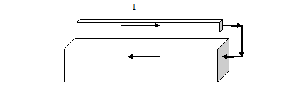
Figure 5 3 A wire carrying a current with return path.
In such a scenario, we need to think of a magnetic field generated not only by the wire but also by the returning current. For the time being, let us consider the number of magnetic lines of loop around the wire on the top. There are magnetic lines of loop around the wire due to the current flowing in it is. There is also magnetic lines of loop around the wire due to the current flowing in the return path. The direction of the magnetic lines of loop due to the return current is opposite to the direction of the magnetic lines of loop due to the current in the wire. The net number of magnetic lines of loops is therefore equal to the difference of these two magnetic lines of loops. The closer these two structures are to each other, the smaller is the number of the net magnetic lines of this loop.
If a changing electric current flows in this structure, then there will be smaller change in the number of magnetic lines of loops and there will be smaller induced voltage generated. This is what is required for a good power supply design.
The inductance of the section of the wire in that case will be the loop inductance or total inductance. This is different from the isolated inductance we were discussing in the previous sections.
Previous - Impedance of Isolated Structure Next -Impedance of Inductor