Verilog Examples - Clock Divide by 3
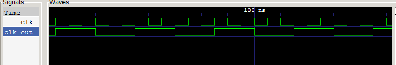
A clock Divide by 3 circuit has a clock as an input and it divides the clock input by three. So for example if the frequency of the clock input is 50 MHz, the frequency of the output will be 16.66 MHz. In other words the time period of the outout clock will be thrice the time perioud of the clock input.
The figure shows the example of a clock divider.
Problem - Write verilog code that has a clock and a reset as input. It has an output that can be called clk_out. The clk_out is also a clock that has a frequency one third the frequency of the input clock. It has synchronous reset and if there if the reset is 1, the outclock resets to 0. Write test bench to verify it.
Solution -
This is the main code clock.v
|
Here is the test bench clocktb.v
|
Explanation
The trick to divide the clock by a negative number is to count at positive as well as the negative edge of the clock
always @(posedge clk) ... ... always@(negedge clk) ... ... |
We basically use a trick to find if the count number for either of the two counters is 2.
assign clk_out = ((pos_count == 2) | (neg_count == 2)); |
You may be tempted to write a single block of always triggering at positive as well as negative edge as in
always @(posedge clk, negedge clk) |
However, it may lead to non sythesizable code as most FPGAs will not support clocking on both edge. We have covered this topic in blog here The rest of the code should be easy to understand
Exercize
1. Modify the code so that it divides the clock by 5. We will have to use 3 bit register to count.
2. Modify the code so that we use a parameter N in the main module. The default value of the parameter is set to 5. In the test bench instantiate the module with N = 7. Verify that it works with new parameter value.
You will find the solutions in the next post.