OrCAD Schematics TUTORIAL
The Design Objective
The purpose of this particular tutorial is to draw a schematics of the following Circuit in OrCAD.
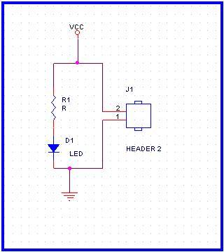
* This is a very simple circuit. Its functionality is to make an led D1 glow when a Power Supply is connected at the connector J1. This is a "hello world" of the Schematics Capture.
* As shown in the Schematics, the circuit uses three components
R1
J1
D1
* Each component will have an associated footprint. We have given the followint names to the footprints of the components used.
| Component | Footprint Name |
| R1 | R0603_1 |
| J1 | HEADER2 |
| D1 | LED |
In the next few pages we will place these three components.