MSP430 Embedded Programming Tutorial TUTORIAL
Understand your Hardware
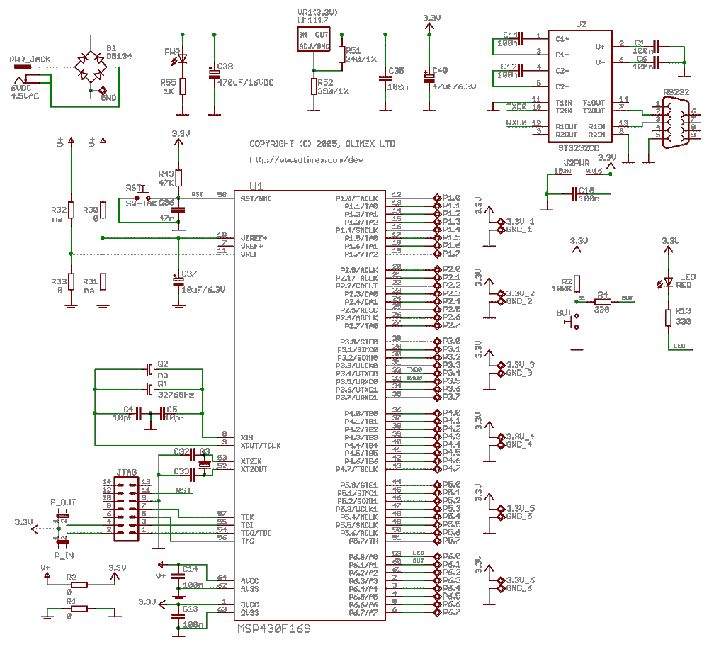
Even before you start learning programming you should spend a small amount of time, to understand the hardware around the Microcontroller that you are going to program. You should open up the Schematics and look at the Input and Output Pins of the Microcontroller. As an Example, take a look at the Schematics below. This Schematics is from Microcontroller shop.

LEDs connected to the Input/Output Pins
For now let us concentrate upon LEDs that are connected to the MSP430F169 microcontrller in the above Schematics. The port Pins P6.0 has LED connected to it. If the Port pin P6.0 is at high or at voltage 3.3, there will no voltage drop accross the LED and the resistor R13. The LED will not glow. If the port Pin P6.0 is at low or voltage 0, there is 3.3V drop accross the LED and the resitor R13. In that case the LED will glow. MSP430F149 have 6 IO ports that can be used as general purpose Input / Output pins. We have connected one them to the LED. We also have connected a push button at port pin P6.1.
The Emulator Connector
In the Schematics, on the bottom left side is a 14 Pin JTAG connector that will connect to the emulator using a 14 Pin connector. Your board can be powered by the USB FET Emulator. You do not need to supply power to the board. The board will need power when it is working on its own.
A bit more about the hardware
There are two things that you will check if you feel that there is some problem with hardware. Check for the power supply voltages. It should usually be 3.0 to 3.3V. If you feel the power supply is good, check for the frequency at the Crystal Oscillator. You will need an Oscilloscope to check crystal frequency.
In the next page we will install the compiler.