Impedance Calculator in Allegro
Let us try to see how we can use the impedance control scheme using Allegro, one of the high end tools. An OrCAD Schematics with two simple connectors is shown below. The net names of these traces are X and Y. It is required that these traces have impedance of 55 Ohms.
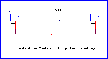
Figure - A simple Schematics to demonstrate Impedance controlled routing.
Calculation using formula method in http://referencedesigner.com/tutorials/si/si_06.php shows that the following arrangement achieves 55 Ohm impedance.
Width of trace = 10 mils Er = 4.5 Height above ground = 7 mils
We have assumed the trace thickness to be 1 mils. A 1 oz trace has thickness of 1.35 mils. But we want to keep the things simple, so 1 oz is good enough for our understanding.

Figure 9.12 - Calculating the impedance from formula using online calculator.
Now let us set the layer stack up in Allegro as follows.
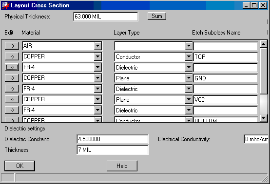
Figure - Setting up layer stackup in Allegro.
It is important that the thickness of the layers and their dielectric be defined as early in the design stage as possible. To find what a given trace width will have a single ended or differential impedance, we can use a built in calculator from Allegro.
Click on Setup -> Constraints > Electrical Constraints Set - > Differential Pair Value - > Calculator >
If you put 10 in the Line Width, the calculator calculates the single ended as well as differential impedance. For now let us focus on the single ended impedance. The allegro calculator gives a value of 56.50 Ohms. This is 1.5 Ohms higher than the formula method.
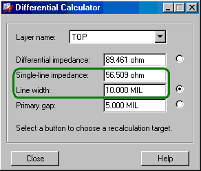
Figure - Single Ended impedance calculator.
Let us now route the traces One with 10 mils width and the other with 20 mils width. The routed net looks something similar to the one below.
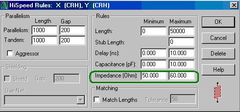
Figure - Setting the Impedance limits for High Speed nets.
Now we will route the net X with 10 mils as calculated. We will route net Y with 20 mils deliberately creating error. Here is how the routed PCB looks like.
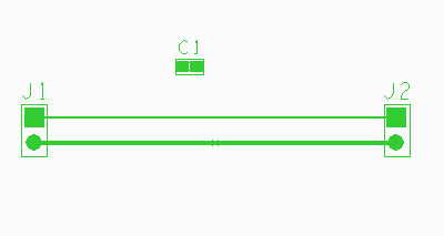
Figure - Routed PCB one net has width 10 mils and other net has width 20 mils.
If you click on Display -> Parasitic, and then click on the 10 mils trace you should be able to something similar to.
TOP CONNECT LINE on network Y

Impedance   : 56.509000 ohm
Inductance  : 11.919700 nH
Capacitance : 3.732760 pF (to SHIELD LAYER)
Prop Delay  : 0.210935 ns
Resistance  : 92.495600 mOhm

Trace model at the picked point (1975000, 1700000)
This gives all the parasitic elements and displays their values. This is a valuable information, as, not only does it gives characteristic impedance value, it also gives inductance, capacitance and Propagation Delay values that can be useful for high speed calculation.
Following is the result for the 20 mils net.
TOP CONNECT LINE on network X

Impedance   : 37.525000 ohm
Inductance  : 8.231450 nH
Capacitance : 5.845680 pF (to SHIELD LAYER)
Prop Delay  : 0.219359 ns
Resistance  : 46.247800 mOhm
Capacitance : 0.59507 pF (to TOP CONNECT LINE on network Y)
A wider trace, has obviously lower impedance and higher capacitance value.
We can also assign constraints to impedance values to a net, so that, it will have impedance in a specified range. To do this click on Edit -> Properties -> Select the net.
In available properties select Impedance_Rule. In the value field enter J1.1:J1.2:50:10. The expected syntax is
LISTING: 1 element(s)

           < DRC ERROR >

  Class:           DRC ERROR CLASS
  Subclass:        TOP
  Origin xy:       (2000.000 1600.000)

  CONSTRAINT:      Impedance
  CONSTRAINT SET:
  CONSTRAINT TYPE:
    Constraint value:
    Actual value:     37.525 ohm

  - - - - - - - - - - - - - - - - - - - -

  Element type:    HORIZONTAL LINE SEGMENT
  Class:           ETCH
  Subclass:        TOP

  part of a connect line
  Part of Net Name: X
The impedance value of the 20 mils trace is 37.25 Ohms and is therefore out of the limit.
Another advantage of assigning the impedance property is that allegro automatically assigns the width of the track based upon the assigned impedance value.
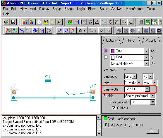
Figure- Allegro automatically assigns trace width 12.533 to target 50 Ohms impedance. Allegro is a versatile PCB editor. You just need to be aware of many of its high speed functionalities to be able to take full advantage of it.
Previous - Impedance Calculator for Microstrip Next - IPC, Wadell and 2D solver comparison