Hspice TUTORIAL
Effect of Capacitive discontinuity
We will now introduce some more imperfections. Let us now introduce a 2pf Capacitor in between the two transmission lines. The hspice code looks as follows.
* Stripline circuit .Tran 50ps 3.5ns .OPTION Post Probe VIN 1 0 PWL 0 0v 250ps 0v 350ps 3.3v Rsource 1 2 40 Tfirst 2 0 3 0 ZO=50 TD=0.17ns C2 3 0 2p Tsecond 3 0 4 0 ZO=50 TD=500ps *Rtermination 4 0 50 .Probe v(1) v(2) v(3) v(4) .End |
This capacitor may represent, for example, a load card on PCI bus. Sometimes a small capacitance of order 0.3 pf may represent a via.
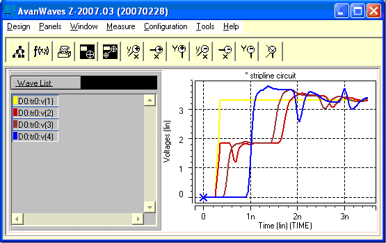
When the signal travels down the transmission line, a part of it is reflected from the capacitor. The reflection is a negative reflection. The resulting waveforms look similar to the waves below.

Figure - Capacitive reflection
Real life simulations will also include driver pin capacitance, receiver load capacitance, package pin parasitics. It is the responsibility of the signal integrity engineer to take into account every component between the transmitter and receiver.
Hspice has the ability to simulate using vendor provided ibis models. This should be used to achieve more accurate results.
In the next page we will learn about the parameters in hspice.