Verilog I2C Master Acknowledment on Spartixed
The Spartixed board has a I2C EEPROM hooked to the Spartan 6. The section of the schematics is shown below
In this section we will write a small code, that will try to detect the presence of the CAT24C08YI-GT3 EEPROM but looking for the acknowledgement signal. If we get an acknowledgement signal when trying to send the I2C address of the EEPRPOM, it will glow an LED, otherwise now. We will test this by sending a wrong I2C device address to make sure that the LED indeed does not glow when the wrong I2C address is sent.
So here is the code that initiates Spartan6 in master mode and looks for ack signal
// i2c Bus Master // This will verify the i2c bus acknowledgement on spartixed board // For details please see referencedesigner.com module i2c (input clk, reset, button_sw3 , output scl, led2,i2c_wp , inout sda ); reg start; reg [7:0] data; reg led_output; reg clk_track; // For simulation use below //reg [2:0] counter; // Actual for division by 1024 reg [9:0] counter; always @(posedge clk, negedge reset ) //always @(posedge clk ) begin if (~reset) begin counter <= 0; end else begin counter <= counter +1; // Use this for simulation // clk_track<= counter[2]; // Division by 8 clk_track <= counter[9]; // Division by 1024 end end wire serclock = (counter ==256); wire sernegclock =(counter ==768); assign scl = ~clk_track; assign i2c_wp= 1'b0; reg [3:0] state; always @(posedge clk) begin case (state) 4'b0000: if (start) state <= 4'b0001; 4'b0001: if (serclock) state <= 4'b0010; // Start bit 4'b0010: if (sernegclock) state <= 4'b0011; // Bit 7 4'b0011: if (sernegclock) state <= 4'b0100; // Bit 6 4'b0100: if (sernegclock) state <= 4'b0101; // Bit 5 4'b0101: if (sernegclock) state <= 4'b0110; // Bit 4 4'b0110: if (sernegclock) state <= 4'b0111; // Bit 3 4'b0111: if (sernegclock) state <= 4'b1000; // Bit 2 4'b1000: if (sernegclock) state <= 4'b1001; // Bit 1 4'b1001: if (sernegclock) state <= 4'b1010; // Bit 0 4'b1010: if (serclock) state <= 4'b1011; // Release Bus 4'b1011: if (sernegclock) state <= 4'b1100; // Read Acknowledgement 4'b1100: if (serclock) state <= 4'b0000; // default: state <= 4'b0000; // Undefined, skip to stop endcase end reg outbit; always @(posedge clk) begin case (state) 4'b0000: outbit <= 1'bz; // idle - May be assign like this outbit <= 1'bz; 4'b0001: outbit <= 1'bz; // 4'b0010: outbit <= 1'b0; // Start Bit 4'b0011: outbit <= data[7]; // Bit 7 4'b0100: outbit <= data[6]; // Bit 6 4'b0101: outbit <= data[5]; // Bit 5 4'b0110: outbit <= data[4]; // Bit 4 4'b0111: outbit <= data[3]; // Bit 3 4'b1000: outbit <= data[2]; // Bit 2 4'b1001: outbit <= data[1]; // Bit 1 4'b1010: outbit <= data[0]; // Bit 0 4'b1011: outbit <= 1'bz; // Release Bus 4'b1100: led_output<= sda; // Read the SDA line default: outbit <= 1'bz; // Bad state output idle better outbit <= 1'bz; endcase end // Output register to pin assign sda = outbit; assign led2 = ~led_output; reg delay_reg ; always @(posedge clk, negedge reset) //always @(posedge clk_track, negedge reset) if ( reset == 0) begin // Correct Address for the I2C EEPROM data <= 8'b10100001; // 1010 is device address, last is 0 means write operation, 1 means read operation // Wrong Address to test // data <= 8'b10101101; // 1010 is device address, last is 0 means write operation, 1 means read operation delay_reg <= 0; //start <=0; start <=1; end else begin delay_reg <= button_sw3 ; start <= (delay_reg) & (~button_sw3); end endmodule |
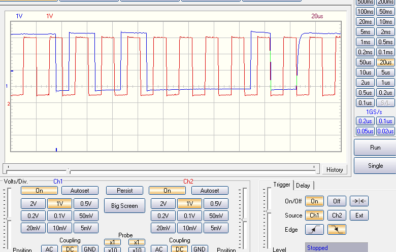
The image shows the screen shot captured on the Spartixed board.
The video about this post is coming soon.
Following ucf file is used.
NET "scl" LOC = P78; NET "sda" LOC = P79; NET "led2" LOC = P131; NET "reset" LOC = P88; // Moved to new Pin as the original not working NET "clk" LOC = P55; NET "button_sw3" LOC = P126; NET "i2c_wp" LOC = P75; |
Suggested Exercises
1. Try to write a byte and then read the byte and then displat it on 7 segment display.