Multiplexing 7 Segment Display in Spartixed
The Spartrixed evaluation board has three seven-segment LED displays. The three seven segment displays have common 8 bit wide data lines, but separate enable lines. By making one of the three ebnable signals high we can display one segment at a time.
To display more than one LED at a time we need to do time multiplexing. In time duration t1 we display the 1st 7 segment display. In duration 2, we display the ' 2nd seven segment display and in duration 3 we display the 3rd 7 segment display and then repeat the sequence. By making the refresh rate fast we ensure that we feel the three segments are being displayed simultaneously.
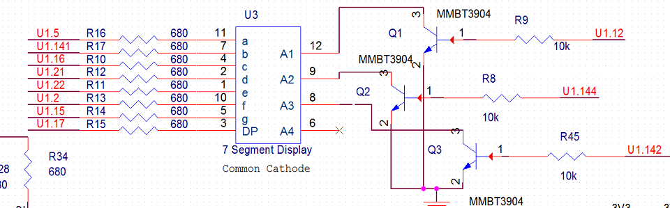
The section of the circuit shows Spartixed's the 7 segment display.
You may also check our section about seven segment display here The code to implemment it is shown below.
module disp_7segment_mux ( input wire clk, reset, output reg [2:0] an, // enable of the three segments output reg [7:0] sseg // led segments ); // refreshing rate around 800 Hz (50 MHz/2^16) localparam N = 18; localparam DISPLAY1 = 8'b00000110; // To display 1 localparam DISPLAY2 = 8'b01011011; // To display 2 localparam DISPLAY3 = 8'b01001111; // To display 3 reg [N-1:0] q_reg; wire [N-1:0] q_next; reg [7:0] in2, in1, in0; always @ (posedge clk, negedge reset) if (~reset) begin q_reg <= 0; in2 <= DISPLAY1; in1 <= DISPLAY2; in0 <= DISPLAY3; end else q_reg <= q_next; assign q_next = q_reg + 1; // Three combinations of the 2 MSB of the counter generate // enable signals for the 7 segment display. always @* case (q_reg[N-1:N-2]) 2'b00: begin an = 3'b001; sseg = in0; end 2'b01: begin an = 3'b010; sseg = in1; end default: begin an = 3'b100; sseg = in2; end endcase endmodule |
The ucf file used is here.
// 50 MHz Input Clock NET "clk" LOC = P55; NET "reset" LOC = P126; // SW3 // Seven Segment Display NET "sseg[0]" LOC = P5; NET "sseg[1]" LOC = P141; NET "sseg[2]" LOC = P16; NET "sseg[3]" LOC = P21; NET "sseg[4]" LOC = P22; NET "sseg[5]" LOC = P2; NET "sseg[6]" LOC = P15; NET "sseg[7]" LOC = P17; NET "an[2]" LOC = P12; NET "an[1]" LOC = P144; NET "an[0]" LOC = P142; |
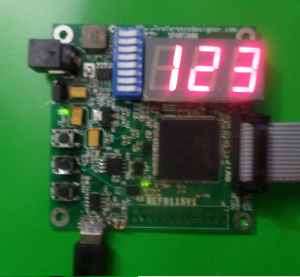
This is how the Spartixed board looks like when we tried to display the characters 1, 2 and 3 on this board.
Suggested Exercises
1. Display 123 in reverse order.
2. Display 000 in the begining and the display should increase to 001, 002 etc on each button press. Use SW2 for this purpose.