Hspice TUTORIAL
Effect of Source Impedance
Let us now modify the hspice code to introduce some real life imperfections and see how it affects the waveforms. Let us change the source resistor to 40 Ohms in the above reflected wave simulation.
The code for this looks as below.
* Stripline circuit .Tran 50ps 3.5ns .OPTION Post Probe VIN 1 0 PWL 0 0v 250ps 0v 350ps 3.3v Rsource 1 2 40 Tfirst 2 0 3 0 ZO=50 TD=0.17ns *C2 3 0 2p Tsecond 3 0 4 0 ZO=50 TD=500ps *Rtermination 4 0 50 .Probe v(1) v(2) v(3) v(4) .End |
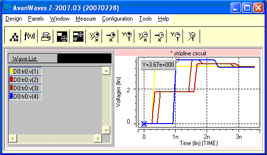
If we run this simulation and observe it on Avanwaves, it should looks something similar to

Figure - Reflected wave simulation with 40 Ohm driver.
The input acceptance voltage in this case is given by
v = viZo/(Zo+Zs).
= 1.83V
This is more than half the 3.3V. This 1.83V wave travels all way to the end of the transmission line and reaches to the end, get reflected and doubles. The amplitude of the wave reflected wave is now 3.67V. This wave travels back toward the source. Since the source termination is not perfect ( i.e., not the same as the transmission line impedance), not all the wave is absorbed. Some part is again reflected. This results in some kind of ringing in the waveform at the receiver end before it settles down.
In the next page we will see the effect of Capacitive discontinuity.